SV Pilgrim - 1979 Morgan 382 - Homeport: Beaufort, NC
Showing posts with label quarterberth refit. Show all posts

Sunday, April 3, 2016

Where Do The Buses Go?

In September 2015, I posted to updates about converting Pilgrim’s 12V Positive Bus into a custom ANL Fuse Block...


Over the winter we installed the custom 12V positive fuse block and the corresponding 12V negative bus.

For those out there asking what is an electrical bus? An electrical bus is simply a distribution or consolidation point along the path the electricity takes to the device the user wants to power. If the electrical wires are like train tracks snaking around a country side then the electrical buses are the train depots that allow people on the main line to switch trains and take side trains to smaller communities and vice-versa on their return trip. The fuses ensure that the outbound trains (positive wires leading away from the batteries) to not become dangerously over crowded with passengers.

Consolidating the electrical wiring components around the nav station is a priority for us.. Installing the buses below the electrical panel offered a centralized location that provided plenty of room for the large gauge wire runs.
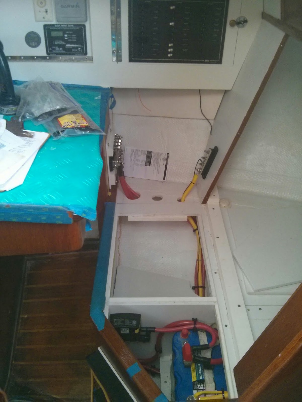


Installing 12V primary wiring and components at Nav Station
Pilgrim's 12V Primary Buses installed below the electrical panel.

Early on in our refit we chose to eliminate the M382’s quarterberth in favor of additional storage space. Eliminating the berth allowed us to create a seat back at the nav station. The middle two panels of the seat back are removable. The outboard seat back panel is fixed. We installed the negative bus on the fixed vertical seat back panel and the positive fuse block / bus opposite along the original nav station structure.

To prevent accidental shorts in a busy area, I fabricated starboard and plexiglass covers for the two buses.
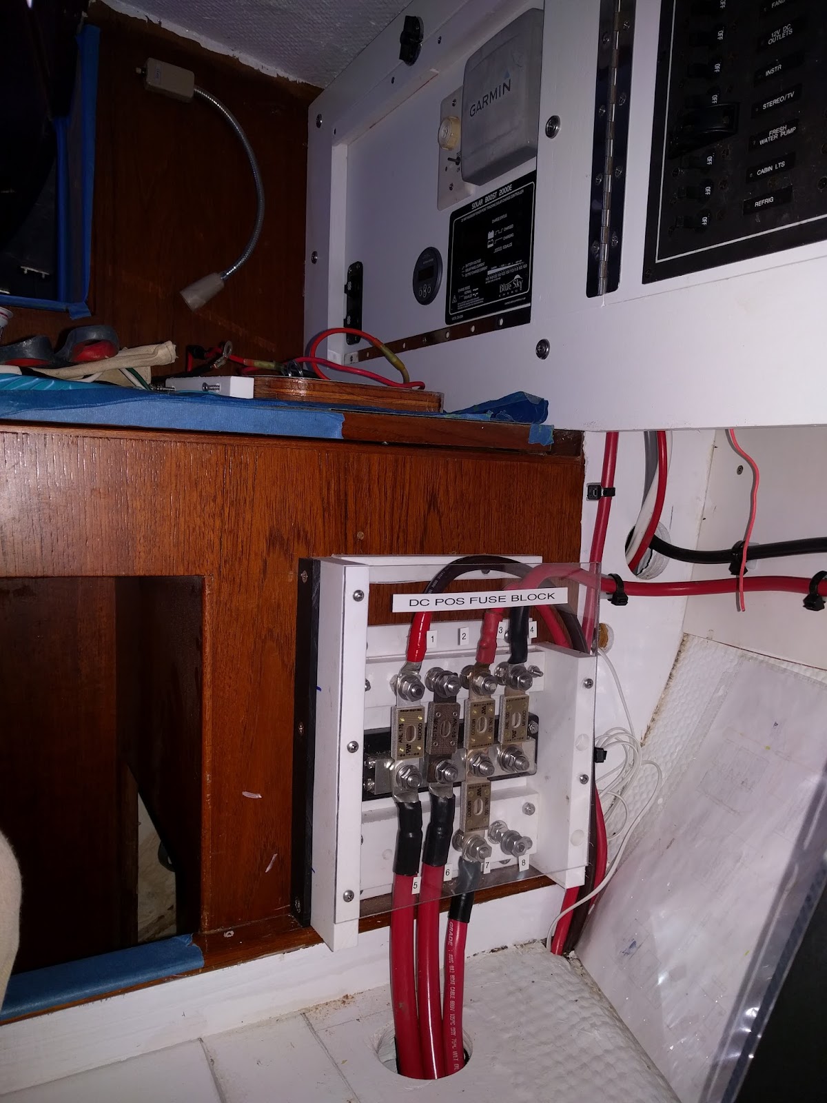
Primary DC Fuse Block Installation
12V Primary Positive Bus / Fuse Block with plexiglass cover.


Progress on Pilgrims nav station.
12V Negative Bus at lower right in image.


The final step was to create a functional armrest to house the unsightly wiring runs and electrical components.
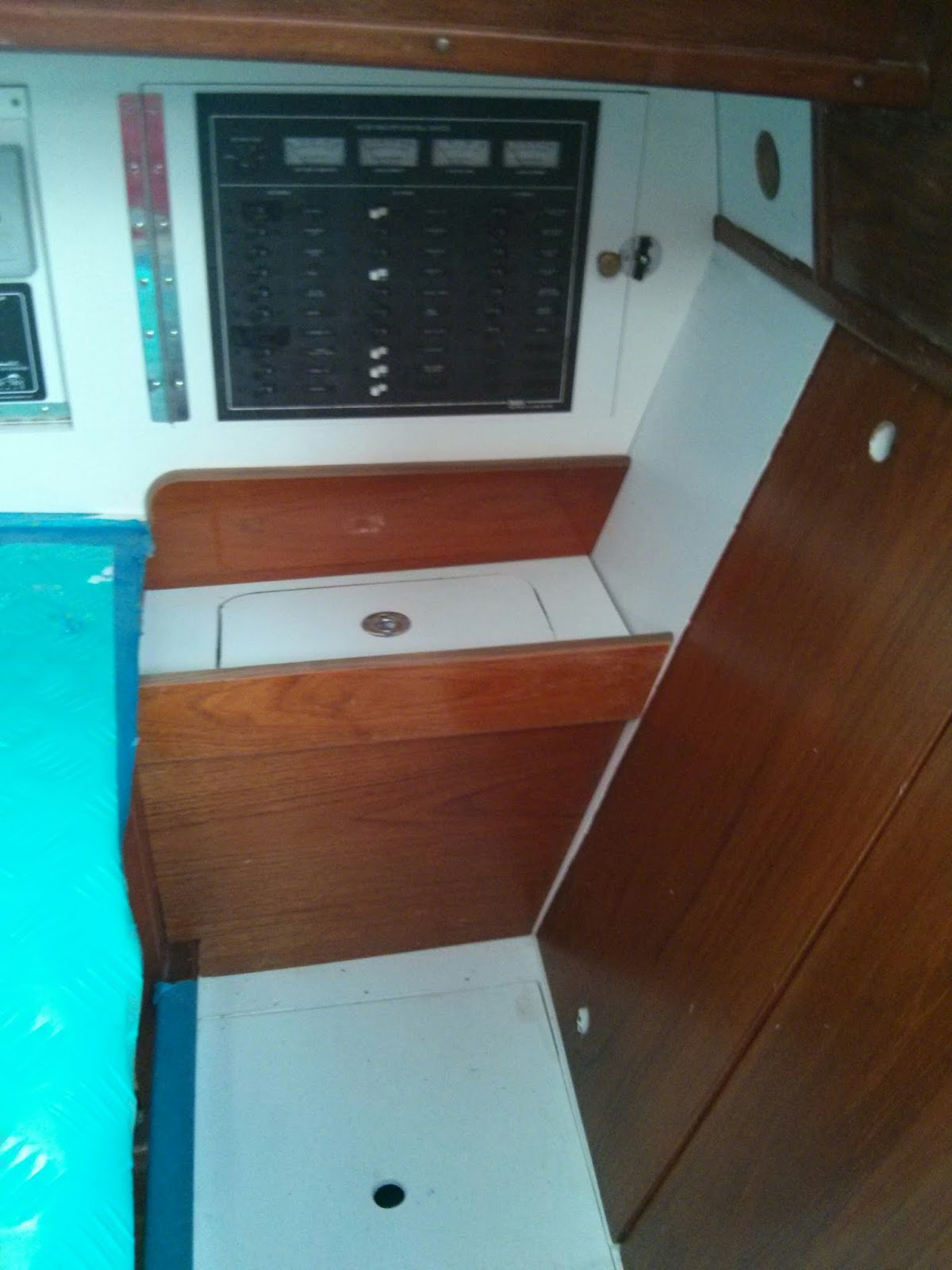
All the pieces in place but need to refinish the fiddle and teak trim prior to final assembly
New arm rest at nav station.
The armrest has a removable panel to allow for storage and quick access to the fuses.

Storage space and access to DC Primary Fuses & Neg bus via removable section.
Removable panel in arm rest allows for easy access to fuses and storage space. 

If additional access is necessary for repairs or upgrades the armrest is designed to easily remove the vertical wood panel via four screws.

Additional photos and notes can be found in our on-line albums.

Re-wiring Pilgrim Photo Album

Nav Station Refit Photo Album

Will post more updates on Pilgrim’s electrical system soon.

Saturday, November 14, 2015

Battery Re-location Project Complete! Before and After Pictures.

I believe Morgan Yachts outfitted the M382’s with the house and starter batteries under the quarterberth on the starboard side of the vessel.  Here is and image of what we found aboard Pilgrim when she arrived in Beaufort, NC in late January 2014.

House battery bank (green) & Starter battery (blue) when we took ownership of Pilgirm

One of our initial projects was to clean up the residual mess and damage in the battery compartment. 

Removing wood cabinetry damaged by battery acid spill.

During this clean up we decided to re-locate the batteries.  Nearly 21 months later we can finally say the we are finished with the effort.

We removed a drawer and storage locker from below the salon seat forward of the galley sinks.

The salon seat forward of the galley sinks - site of the future house battery bannk.

We fabricated and installed a battery box capable of storing six 6V batteries.  This will be Pilgrim’s new house bank.

House bank install complete.
Two removable panels conceal the battery bank.

Battery bank closed.  We installed vents on the forward and starboard sides of the cabinetry.

We used the opening and the door face from the original drawer to create access to the battery monitor shunt, battery switch, and ANL Fuse.

Hinged access to shunt, battery switch, and ANL fuse.

Back at the quarterberth, we removed the deck and gutted the original dividers.

Deck and dividers removed from quarterberth.

We tabbed new dividers to the hull and created four new lockers… two outboard for storage; inboard and aft for the engine raw water thru hull and strainer, inboard and forward for the starter battery.

New dividers and deck in quaterberth.

In addition to the start battery the inboard forward compartment also houses the automatic charging relay, bilge pump switches, and the battery control panel.

Looking down into locker containing ACR, Start Battery, & wiring for bilge pumps and battery control panel.

The battery and bilge pump panel is located below the navigation station bench seat.  This is the site of the original battery selector switch.

Battery control & bilge pump switch panel below nav station seat.


For additional images and notes check out our – Battery Relocation Photo Album

Saturday, September 12, 2015

Replacing the Leaking Quarterberth Port, the Exterior Story – Part 2

Part 1 of the Exterior Story focused on shaping the window pane (Link: Replacing the Leaking Quarterberth  Port, the Exterior Story – Part 1.)  Thanks to everyone the left suggestions and links on the last post.  Now we are on to installing the window.

Drilling over-sized holes for fasteners in the acrylic window pane.

Due to thermal expansion / contraction the pilot holes for mechanical fasteners need to be over sized.   I also drilled a slight counter sink on the exterior pilot holes to provide space for butyl tape bedding.  This work was all done on a drill press.

Clamping window in place to test fit, mark fastener locations, and scribe window opening on interior face.

The window moved from the drill press to a test fit on Pilgrim.   While the window was clamped in place we marked the fastener locations on the exterior.  On the interior we used a marker to  trace the window opening  onto the masking.

Using a marker to trace the interior window opening onto the masking.

After removing the pane, we gently ran a razor blade along the outline of the opening on the interior of the window.  This allowed us to remove the section of masking in contact with the hull while leaving the remaining window masked.  We then drilled the pilot holes the cockpit wall.

Acrylic in contact with hull exposed and pilot holes drilled.

We are using #12 stainless steel pan head screws to mount the window.  To allow for thermal expansion we included a neoprene washer between the head of the screw and the pane of acrylic.  The screws are bedded with butyl tape.  We are also using butyl tape to bed the window.

Applying butyl tape to fasteners and acrylic.

We applied three rings of ¾” wide X 1/8” thick butyl tape to the exposed acrylic on the interior face of the pane.  We have found Amazon to be a good source for butyl tape.  Here is a link to the tape we are using on this project – Dicor Butyl Tape. 

Fortunately the installation occurred on a hot, sunny day.  Both the acrylic and the butyl tape are easier to work with when they are warm.  In cold temps the acrylic is less flexible and more prone to cracking.  The cold butyl tape is much more firm and less likely to form into a good seal.  If completing this project in the winter, then we would have used a heat gun to warm the assembly prior to attempting the installation.

The installation went smoothly.  We over tightened the pane slightly until we observed butyl tape squeezing out around the entire perimeter.  Then we backed off the screws until the neoprene washers returned to their original shape ( approximately ¼ to ½ a turn.)

Using a plastic "knife" to remove the excess butyl tape

We use a plastic “knife” to cut away the excess butyl tape.

The completed installation.

After completing the install, overnight thunderstorms confirmed the new window is water tight.


See our Cockpit Refit Photo Album for additional images and other projects associated with the cockpit.

Friday, September 4, 2015

Replacing the Leaking Quarterberth Port, the Interior Story.

While sanding in the engine compartment, a passing a rain shower alerted me to how badly the old, plastic quarterberth port was leaking.  All the other ports in the Pilgrim are New Found Metal Stainless Steel ports, installed by a previous owner.  Replacing the only remaining original plastic port was on the project list.  Watching row of steady drips along the starboard side wall of the engine compartment elevated the project priority.

We believe the plastic port in the quarterberth was installed at the factory in 1979.

Frequently after rains I check the quarterberth area for water intrusion.  Never found any signs the port was leaking.  It never occurred to me to check the engine compartment.  The leak originated around the outer flange of the port. The water then dripped down thru the void between the fiberglass wall of the cockpit foot well and the ¾” plywood cabinetry wall of the quaterberth.

The original port, set in copious amounts of silicone sealant, heartily resisted removal.  Ultimately the combination of a razor knife and pry bar won the day. 

The exterior view of the hole remaining after the port was removed.

After sanding down the surrounding surfaces, I filled the nearly 1-1/2” wide void around the perimeter of the opening with trimmed down pieces of a pressure treated 2” X 4”.

Fitting treated wood plugs into the void around the perimeter of the opening.

The wood plugs fit snuggly.  Once in place, I mechanically fastened the wood filler to both the outer fiberglass and the interior plywood using flat head stainless steel screws.

Filling gaps and irregularities around the opening with thickened epoxy.

Next, the remaining gaps and irregular surfaces were filled with cabosil thickened epoxy.  After sanding down the initial round of epoxy filler, the fairing began.

Round one of fairing viewed from the interior.

Fairing required two rounds of epoxy thickened with a micro-balloon filler (q-cells).  Each round of filler was followed by additional sanding.

Two rounds of fairing completed.  Now ready for primer.

The interior surfaces were finished with two coats of latex primer and two coats of exterior grade latex paint.

The interior completed.  Test fitting the masked acrylic window pane.

Since we intend to use Pilgrim’s quarterberth  as a storage area only, we chose to install an acrylic window pane rather than a new opening port.  We realize not installing an opening port will reduce ventilation in the area.  We have scrap pieces of tinted acrylic on hand.  New ports are very expensive.  Using the acrylic will save us money.  The window will provide natural lighting for the storage area.

View from the interior with the new window installed.

See our Quarterberth Refit Photo Album for images and notes current progress on this project.


Next up, the outside story… fabricating and installing the new acrylic window pane.

Friday, July 31, 2015

Nav Station Instruments and Electrical Panel Façade – Part 2

Installing panels in the frame required creative hinge work.

Test fitting new nav station electrical and instrument panels.

To provide the most ergonomic access to the backside of the panel we chose to hinge the aft, electrical panel section along the forward, vertical side.  Hinging the panel to swing forward provides easy access to the panel while sitting at the nav station.   It also places additional stress on the hinge.  To accommodate the additional forces I chose to surface mount the hinge. Then thru-bolted machine screws to attach the hinge to the panel. 

The BassPanel contains 20 D/C breakers, 8 A/C breakers, an A/C reverse polarity indicator, analogue load gauges for both D/C & A/C systems, and analogue voltage gauges for both D/C & A/C systems.

Being uncertain what devices may be added to the forward panel in the future, I felt the best option was to place the hinge along the lower, horizontal edge of the panel.    Thus panel swings down and rests atop the nav station desk.  This action provides access to the back side of the panel while sitting at the nav station.  Accessing the items mounted on the hull outboard of the panel can be achieved by kneeling on the nav station bench seat.

The forward, instrument panel hinges down.  The aft, electrical panel hinges forward.

I recessed the foreword panel slightly by installing the hinge to the vertical face of the panel and the horizontal edge of the frame.  This provides additional clearance between devices installed in the panel and the hinged nav station desk top that swings upward when opened.

The final install will include trim along the top and an arm rest / storage below the aft section.

Currently panel is simply slid into place for test fitting.  For the final installation we will secure it with screws and add trim along the top edge.  We also plan to build an arm rest / storage below the electrical (aft) panel.  The arm rest will hide the wire runs entering the panel from below.


See our Navigation Station Re-Fit Photo Album for images and notes current progress.

Thursday, July 23, 2015

Prep Work for Nav Station Electrical Panel Upgrades

When we purchased Pilgrim it came equipped with the original 1979 Morgan Yachts electrical panel.

Original 1979 Morgan Yachts Electrical Panel.  We sold this panel to another Morgan Owner.

While still fully functional, this panel lacked the appropriate number of DC breakers to accommodate the system upgrades we have planned.  Due to the large analog meters and double pole AC breakers the panel also has a large footprint relative to the number of breakers.

Most of the original wiring associated with the panel was shoe horned into a tiny area below the interior of the nav station storage.  Since we plan to expand the number of circuits, we will also need more space to mount the “back end” (terminal blocks, bus bars, etc.) of the electrical system.  Our plan is to install plywood panels along the hull out board of the nav station.  These panels will provide a large vertical surface area for mounting various components of the electrical system.

First step of the process is to identify the location and orientation of the frames.  Frames are typically wood strips secured to the hull, typically with epoxy, that provide a mounting surface on to which interior structures (i.e. cabinetry, ceiling panels, wall coverings, etc.) can be mechanically fastened. 

X marks the areas need to be ground down to bare fiberglass.

The hull outboard of the nav station has little curvature and our access is limited thus orienting the four frames horizontally worked better in this location.  The lower, forward frame location is eclipsed by the nav station desk in most of the included images.

We plan to epoxy the frames to the hull so the next step is to grind the area under the frames down to bare fiberglass.  Time to suit up and make some dust…yuck.

Grinding complete.  Now where is the shop vac?

We have some of the original frames Morgan used for the headliner as spares so we recycled them for this project.  Thickened epoxy was then used to bond the frames to the hull.

Recycling unused headliner frames for the new electrical panel.

Once the frames were cured and permanently in place, we added a single layer of 3/16” reflectix insulation along the hull.

On a whim we added a layer of 3/16" thick reflectix insulation along the hull.

A few weeks ago we used some cardboard templates to begin laying out the electrical system.

Cardboard templates of the new panels are used for experimenting with the electrical system layout.
We used 3/8” plywood pre-coated with white Formica to create the panels.  These are attached to the frames using counter sink, flat head screws.

Ahh... a blank canvas for creating the new electrical system.

We now have plenty of real estate for mounting the new electrical system.

We drilled a few large diameter holes far outboard in the nav station seat.  These will be used for future wire runs.  Our plan is to cover the wire runs with a arm rest / storage cubby once the electrical system is in place.


See our Navigation Station Re-Fit Photo Album for images and notes current progress.

Thursday, June 25, 2015

Adding Above Water Thru-Hulls for Deck & Bilge Pump Drains

We have added two new 1-1/2” thru-hulls above the water line.  The port thru-hull will serve as the discharge for the upper, larger capacity bilge pump (3700 G/H).    

The starboard side thru hull will act as a drain for the deck scupper.  We did not like the long hose run from the starboard scupper to the torpedo tube drain manifold.  We also wanted to rig a method for collecting water off the deck if necessary. 

Prior to drilling any holes we assembled the new starboard deck drain plumbing.
Test fit of new plumbing for starboard deck drain.  Note old drain hose at far right.

Test fitting the new plumbing allowed us to accurately mark the location for the starboard thru hull.   The port side fitting connects to a single flexible hose so identifying the exact location was less critical.

Since the location of the holes was marked on the inside of the hull, I began the drilling using a ¼” bit to drill a pilot hole from the inside out.  The ¼” hole matches the diameter of the hole saw pilot bit.  Next, I chucked a 1-7/8” hole saw into the drill and moved outside the hull.  Drilling the larger hole from outside allows for properly aligning the hole perpendicular to the hull and creates less dust inside the boat.

We drilled two 1-7/8" holes in the hull.

The Morgan 382, 383, & 384 hull’s have a foam core above the waterline.  This is the first time we have drilled large diameter holes above the waterline and subsequently our first look at the coring material. 

Close up of plug offers a glimpse of Morgan's construction techniques.

The hull is slightly over one inch thick… the outer fiberglass layer is 5/16”; the foam 9/16”; and the inner fiberglass layer 1/8”

Placing holes in cored hull’s or decks requires additional effort to ensure water never reaches the core material.  In smaller, fastener sized, holes this can be achieved by over drilling the size of the hole and then filling it back with epoxy.  Larger holes for plumbing fixtures require a different approach.

Using a small flat screw driver and a couple different styles of picks, we removed all the coring material within approximately ½” of the hole.

Foam core removed from the area around the hole.

The plan is to fill the newly created void around the hole with thickened epoxy.  So the next couple steps are the usual epoxy prep… 80 grit sanding, acetone wipe down, mask area...  We used a syringe to apply the epoxy and a plastic spreader to achieve a nice clean finish.

Filling the area around the hole with thickened epoxy.

After a couple days for the epoxy to fully cure, we returned to the project.  Using a #49 cabinet rasp and some 80 grit sand paper, Anne cleaned up any excess epoxy from the holes.  While I cut down the length of the threaded section of the thru-hull to properly fit the valve on the starboard side.

Prior to applying any sealant we dry fit the two thru-hulls and masked the surrounding area.  For the final install we used 3M 5200 sealant. Anne worked the interior and I the exterior.

New thru hull fittings are just above the waterline and five feet forward of the torpedo tube drain on either side of the hull.

We are still waiting on hose to connect the bilge pump to the new fitting on port, but we wasted no time installing the new starboard deck drain plumbing. 

New deck drain w/ option for filling water jugs installed.
Since the installation we have weathered a couple heavy rains.  The starboard deck scupper is performing much better with the new system.

What was that you said? 


Why yes that is a new battery selector and bilge pump switch panel in the image above.  I’ll post more info on that project very soon.

Monday, June 15, 2015

The Mental Exercise Prior to the Physical Progress

Spending time to fully plan out a project, or at least one component of a large project, prior to making that first cut, boring a pilot hole, or applying an initial layer of epoxy is a wise investment. 

The time I devote to creating templates and testing designs is definitely increasing as my experience working on boats expands. Or perhaps as the size and cost of the boats on which I work is increasing.  I vividly recall the trepidation with which I approached drilling a hole for a drain plug in a new plastic whitewater kayak over twenty years ago.  Now I find myself boring 1-7/8” holes in the hulls of custom built offshore sailing vessels that are closer to 100’ than the length of that long ago kayak.  Perhaps expending time planning prior to action equates to wisdom gained through time and experience, I am, at least chronologically speaking, what most Americans consider middle age.   

Ok, enough philosophical musing.  Let’s talk boat projects.  I’m in the head scratching, throw pasta at the wall and see what sticks, scrap that idea and move on to the next portion of three different projects.

Ice Box Lids…

Test fitting lids after completing modifications to the box.

The fabrication of a new ice box is complete, save for those damn lids.  I cannot figure out how to best add insulation to the inside of the lids and insure a good seal along the opening.

Notes from experimenting with various methods of insulating the lids

Never thought the lids would be the most difficult aspect of the re-build.  See our Ice Box Rebuild Photo Album for images of the latest progress.


Plumbing Drains…

Myriad of plumbing fittings.  Remind anyone of days spent playing with Legos or Tinker Toys?

In an effort to reduce the length of hose runs and not feed too much water to the drain manifold (see – New Deck & Bilge Pump Drain Manifold) we are adding two 1-1/2” thru-hull fittings above the waterline on opposite sides of the hull.  The port fitting will serve as a discharge for the upper, 3700G/H bilge pump.  The plumbing associated with this system required only minor experimentation.

The starboard thru-hull act as a drain for the deck scupper.  As with our previous vessel (SV C’est la Vie) we want the ability to fill water jugs from the deck scupper. The ability to collect (then filter) rain water off the deck proved very helpful on our last extended trip in the islands. 

Test fitting the final draft of the new starboard deck scupper plumbing.

The mechanics of the plumbing took some time to work out. We definitely want to have the details worked out prior to drilling the hole in the hull.  See our Quarterberth Re-fit Photo Album for the current progress on this project.

Electrical Panel…
Designing the inner workings of the electrical panel from scratch is both enticing and daunting.  I began by creating cardboard templates of the space available.

Cardboard templates of the space available for the electrical panel wiring. 

I then experimented with the layout of terminal strips and busbars atop the templates using different color pens to illustrate AC & DC wire runs.

Experimenting with the layout of AC & DC wiring, terminal strips, and busbars.  

Once satisfied with the layout, I taped the templates into position.

Test fitting the electrical panel template in position along the hull.

Then made a few more modifications to the design.  

See our Navigation Station Re-Fit Photo Album for images and notes current progress.


The planning continues.