SV Pilgrim - 1979 Morgan 382 - Homeport: Beaufort, NC
Showing posts with label 12V System. Show all posts

Sunday, April 3, 2016

Where Do The Buses Go?

In September 2015, I posted to updates about converting Pilgrim’s 12V Positive Bus into a custom ANL Fuse Block...


Over the winter we installed the custom 12V positive fuse block and the corresponding 12V negative bus.

For those out there asking what is an electrical bus? An electrical bus is simply a distribution or consolidation point along the path the electricity takes to the device the user wants to power. If the electrical wires are like train tracks snaking around a country side then the electrical buses are the train depots that allow people on the main line to switch trains and take side trains to smaller communities and vice-versa on their return trip. The fuses ensure that the outbound trains (positive wires leading away from the batteries) to not become dangerously over crowded with passengers.

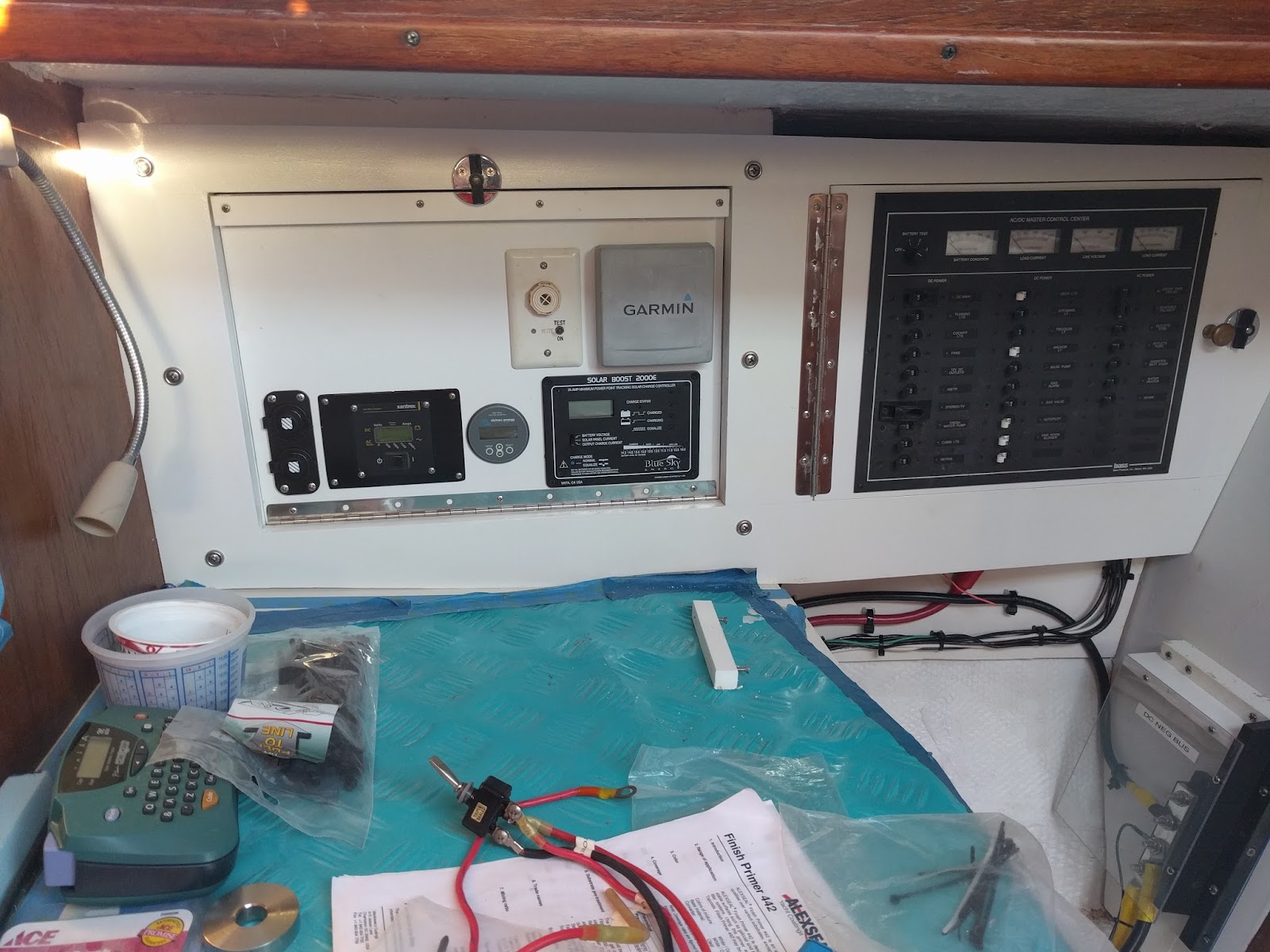
Consolidating the electrical wiring components around the nav station is a priority for us.. Installing the buses below the electrical panel offered a centralized location that provided plenty of room for the large gauge wire runs.


Installing 12V primary wiring and components at Nav Station
Pilgrim's 12V Primary Buses installed below the electrical panel.

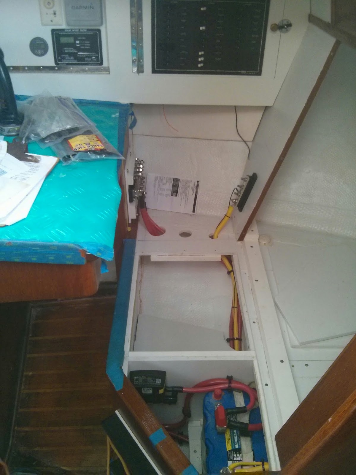
Early on in our refit we chose to eliminate the M382’s quarterberth in favor of additional storage space. Eliminating the berth allowed us to create a seat back at the nav station. The middle two panels of the seat back are removable. The outboard seat back panel is fixed. We installed the negative bus on the fixed vertical seat back panel and the positive fuse block / bus opposite along the original nav station structure.

To prevent accidental shorts in a busy area, I fabricated starboard and plexiglass covers for the two buses.
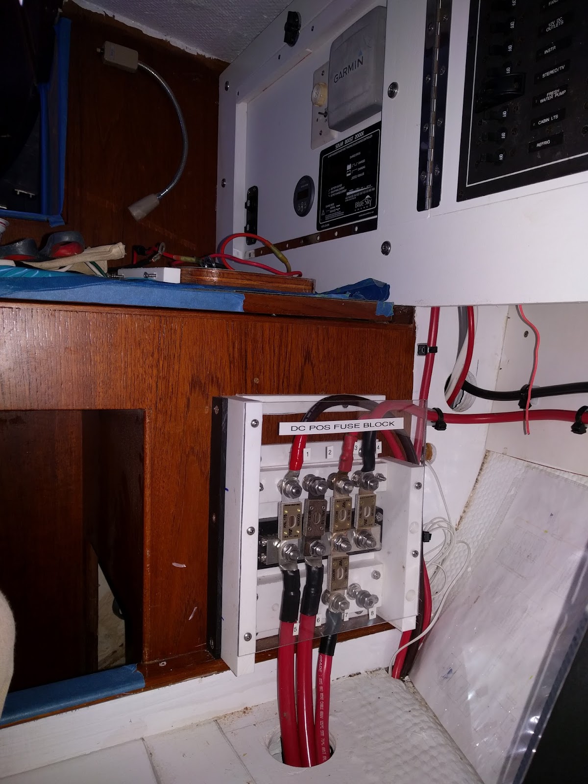
Primary DC Fuse Block Installation
12V Primary Positive Bus / Fuse Block with plexiglass cover.


Progress on Pilgrims nav station.
12V Negative Bus at lower right in image.


The final step was to create a functional armrest to house the unsightly wiring runs and electrical components.
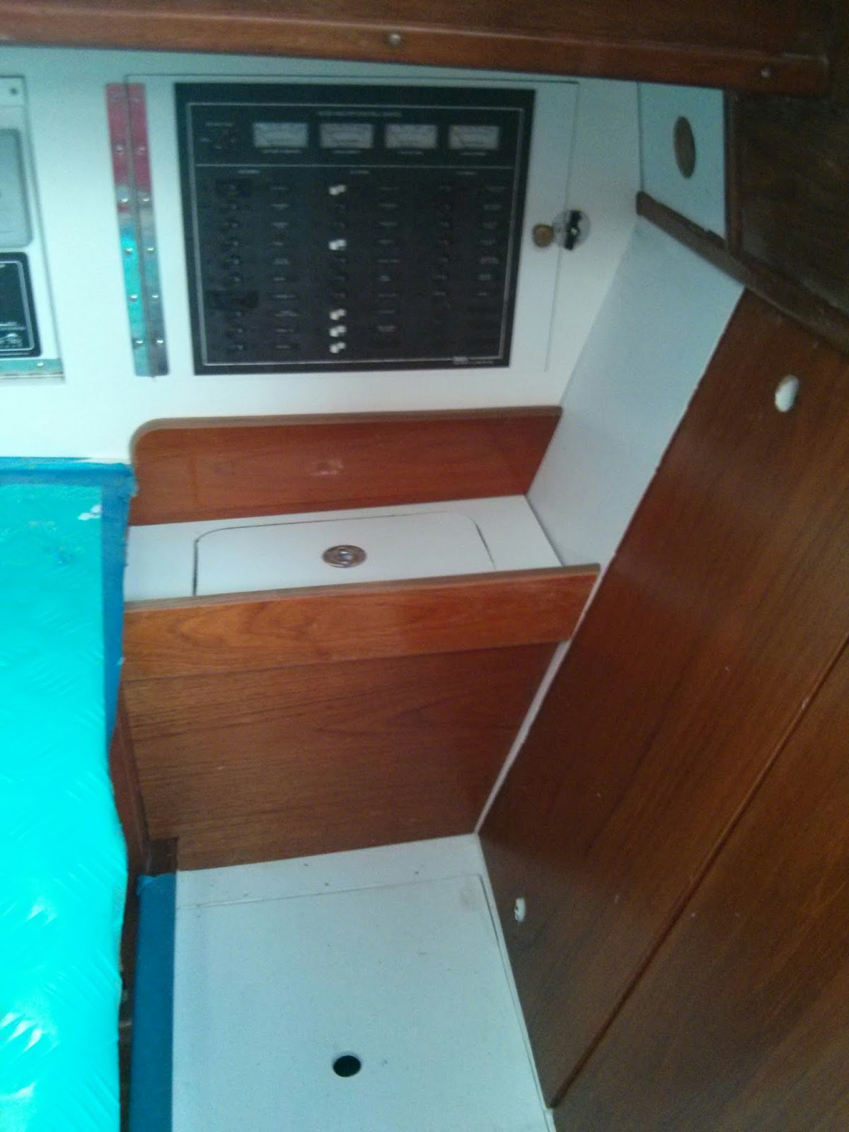
All the pieces in place but need to refinish the fiddle and teak trim prior to final assembly
New arm rest at nav station.
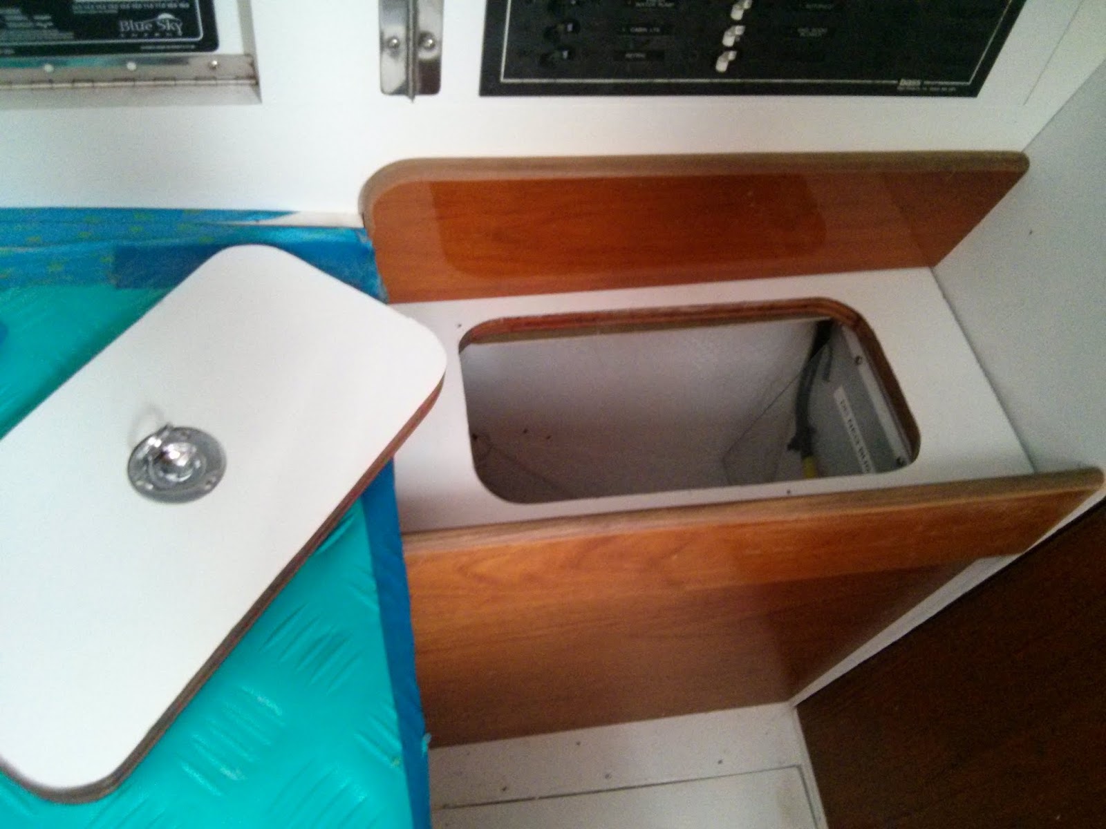
The armrest has a removable panel to allow for storage and quick access to the fuses.

Storage space and access to DC Primary Fuses & Neg bus via removable section.
Removable panel in arm rest allows for easy access to fuses and storage space. 

If additional access is necessary for repairs or upgrades the armrest is designed to easily remove the vertical wood panel via four screws.

Additional photos and notes can be found in our on-line albums.

Re-wiring Pilgrim Photo Album

Nav Station Refit Photo Album

Will post more updates on Pilgrim’s electrical system soon.

Saturday, November 14, 2015

Battery Re-location Project Complete! Before and After Pictures.

I believe Morgan Yachts outfitted the M382’s with the house and starter batteries under the quarterberth on the starboard side of the vessel.  Here is and image of what we found aboard Pilgrim when she arrived in Beaufort, NC in late January 2014.

House battery bank (green) & Starter battery (blue) when we took ownership of Pilgirm

One of our initial projects was to clean up the residual mess and damage in the battery compartment. 

Removing wood cabinetry damaged by battery acid spill.

During this clean up we decided to re-locate the batteries.  Nearly 21 months later we can finally say the we are finished with the effort.

We removed a drawer and storage locker from below the salon seat forward of the galley sinks.

The salon seat forward of the galley sinks - site of the future house battery bannk.

We fabricated and installed a battery box capable of storing six 6V batteries.  This will be Pilgrim’s new house bank.

House bank install complete.
Two removable panels conceal the battery bank.

Battery bank closed.  We installed vents on the forward and starboard sides of the cabinetry.

We used the opening and the door face from the original drawer to create access to the battery monitor shunt, battery switch, and ANL Fuse.

Hinged access to shunt, battery switch, and ANL fuse.

Back at the quarterberth, we removed the deck and gutted the original dividers.

Deck and dividers removed from quarterberth.

We tabbed new dividers to the hull and created four new lockers… two outboard for storage; inboard and aft for the engine raw water thru hull and strainer, inboard and forward for the starter battery.

New dividers and deck in quaterberth.

In addition to the start battery the inboard forward compartment also houses the automatic charging relay, bilge pump switches, and the battery control panel.

Looking down into locker containing ACR, Start Battery, & wiring for bilge pumps and battery control panel.

The battery and bilge pump panel is located below the navigation station bench seat.  This is the site of the original battery selector switch.

Battery control & bilge pump switch panel below nav station seat.


For additional images and notes check out our – Battery Relocation Photo Album

Saturday, October 31, 2015

Securing the House Battery Bank

One of the final components of re-locating the house battery bank was securing the batteries. 

Per Full River’s Specs each 6V battery weighs in at approximately 66 pounds.  Presently our house bank consists of four 6V batteries = 264 pounds.  We plan to expand the bank to six 6V batteries = 396 pounds.   Preventing this 400 pound mass from sliding around during normal conditions is critical to the long term health of our electrical systems.  Eliminating the possibility of this 400 pound mass from becoming a projectile in the event of a knockdown is critical to life and limb.

We designed the new battery box to fit snugly around the batteries.  The fit will limit side to side and fore to aft motion of the batteries.

Installing the new fiberglass over plywood battery box in the space under the center salon seat.
The new battery box is mechanically fastened, six ¼” counter sunk, flat head screws, to the Morgan 382’s internal glass unit (IGU).  The IGU is a structural member in the Morgan’s hull that provides strength to the hull and a mounting surface for the cabin sole.

Since we are two batteries shy of our desired six battery house bank, we constructed temporary filler to prevent the existing bank from sliding fore and aft.

Four 6V batteries plus the temporary filler in the new box.

Ok, this set up takes care of movement under normal conditions. 

Next we installed the system’s wiring.

House battery bank wiring complete.

We installed the wiring to allow space for bars to run across the top of the batteries.  Initially I envisioned having some stainless steel bars fabricated to fit across the space, but custom fabrication = $$$.  In the end we decided to keep it simple.

We purchased two 3’ long sticks of ½” diameter stainless steel all thread rod. 3’ was more than enough length to span the distance across the top of the battery box and thru both adjacent 3/4" plywood walls.

Using the 1/2" all thread rod to locate the hole on bulkhead aft of the battery box.

We began by drilling a ½” diameter hole in the plywood wall forward of the battery bank.  Running the rod through the hole and across the top of the battery bank aided in locating the position for the hole on the wall aft of the battery bank.  After drilling all the holes and test fitting the rods, we removed the rods and  cut them the proper length.

We sheathed the rods in 5/8" id hose. 

When re-installing the rods, we sheathed them in 5/8” id hose to prevent chafe or the possibility of a loose wire shorting out to the steel rod.

The ends of the rods are secured with nuts on both ends.

Nuts and washers installed on the ends of the rods under the galley sink (center, right below black water pump).
Nuts and washers installed on forward face, below the center salon seat.

We are confident the batteries are secure.  The next and final step in our battery re-location project is to fabricate a lid for the new house bank installation.


Please check out our Battery Re-location Photo Album for additional images and notes on this project.

Saturday, October 24, 2015

Crimping Lugs onto Large Gauge Electrical Wires

Our recent installation of Pilgrim’s primary 12V DC wiring required the numerous large gauge, 4 to 00, electrical wires.  If you’re wondering which is the larger wire a 4 or 00, then check out our previous post – Let’s Talk Marine Wire, October 18, 2015.

Large gauge wire runs at electrical panel and starter battery.
Large gauge wire runs at house battery bank.

Here are a few things I picked up about crimping lugs onto large gauge wires.

Happiness is having the right tools for the job at hand.  The key for installing wire terminals on large gauge wire is having the proper crimping tool.   Unfortunately appropriately sized, quality crimpers are expensive and rarely part of the DIY sailor’s quiver of tools.  Fortunately I am currently able to borrow a great crimping tool with dies for crimping 6ga through 4/0ga. 

If anyone out can recommend a source for purchasing a quality pair of crimpers functional on 6 to 2/0 wire, then please share the info in the comments.

Tools and materials:  Clockwise from the top - heat gun, medium duty wire cutters (blue handle), large gauge wire crimper with multiple dies, 2/0 x 5/16 post lugs, heat shrink tubing,  2/0 wire.

Heavy duty wire cutter and a sharpie style marker are essential tools missing from the image above. 

I’m not certain if there is a technical difference between lugs and ring terminals.  In my vernacular ring terminals are used with smaller gauge wire and typically have heat shrink insulation already installed.  Lugs are typically non-insulated fittings for larger wire.  If anyone out there has a different definition / delineation, then please let me know.

22ga to 8ga insulated ring terminals on left.  6ga to 2/0ga lugs on right.
Ring terminals and lugs need to be sized to the correct gauge of wire and to the correct post diameter.  In the image below both lugs are for 2/0 wire.  The lug on the right fits a 3/8” post and the one on the left fits a ¼” post.

Two 2/0ga lugs with holes for different size posts.

Avoid aluminum when purchasing wire connectors.  Like marine wire all terminals and lugs should be tinned copper.

I’ve found my medium duty wire cutters will realistically work on wire up to around 1 gauge.  0 through 4/0 wire will require large cable cutters.  Sailing vessels should be carrying large cable cutters to deal with wire rigging in the event of a dismasting (See our C’est la Vie post: Dis-masted – Part 2 if you doubt the necessity of having large cable cutters aboard.)  Cutting 4/0 wire is easy with the large cable cutters. 

Once the wire is cut to the proper length, slide a section of heat shrink tubing for each lug to be installed onto the wire.  Sliding the heat shrink over the wire at this point will aid in avoiding any fraying of the wire once the insulation is removed.  Next, using the lug as a guide mark the amount of insulation to be stripped off the end of the wire.

The medium duty wire cutters are my tool of choice for stripping wiring larger than 10 gauge.

Stripping 2/0 wire using medium sized wire cutter.

Apply gentle pressure to the handles while rotating the cutters around the wire.  I prefer to rotate back and forth through 180 degrees.  Rotating through 360 degrees is ergonomically awkward and often results in a spiral cut on the insulation.  Stop the motion when you begin to feel the strands of copper against the edge of the cutters. Knowing when to stop cutting and how much pressure to apply comes with practice. 

Once the insulation is gone, I move directly to installing the lug.  Expediency at this step will aid in avoiding any fraying of the small stands of copper wire. 

Crimping a lug on a 2/0 battery cable.

Once the crimping is completed, I give the lug a through visual quality inspection.  If satisfied with the connection, then slide the heat shrink tubing over the junction and let the heat gun do the rest.

Numerous 2/0ga battery wires in Pilgrim's house battery bank.


Happy Crimping!

Sunday, October 18, 2015

Let's Talk Marine Wire

Within days of Pilgrim arriving in Beaufort, Feb. 2014, we removed all of the existing wiring.

Creative and dangerous wiring in Pilgrim's bilge.

34 years of modifications and repairs to the electrical system by many hands left a hodgepodge of wiring.  Almost all of the wiring was sub-standard.  Some was outright dangerous - note unfused bilge pump wire run joined with wire nuts in image above – YIKES!

Unfortunately Morgan Yachts did not use marine grade wire in the original construction.

Factory installed shore power circuit breaker removed from Pilgrim.

So all the original wiring was also removed.

Gutting the original electrical panel.

All the wire going back into Pilgrim is marine grade.  So what makes marine grade wire different from home or automotive wiring?

  • Marine grade wire is composed of tiny copper strands.  The wiring in a land based structure is typically a single thick copper wire. Stranded wire has more flex.  This allows the wire more easily fit into the tight spaces on a small vessel while placing less stress on connections.
  • All the tiny strands of copper in a marine grade wire are tinned (plated with tin.)  The tin coating protects the copper from corrosion due to moisture and heat.
  • The plastic insulation covering the exterior of marine grade wire is designed to resist degradation if exposed to fuel or oil.  This is very important for wiring in bilges and engine compartments.


What about the size of the wire (yes it does matter – haha.)  Size of electrical wiring here in the USA is designated by the American Wire Gauge (AWG). Wiring on marine vessels can vary from tiny 22 to 26 AWG in electronics and NMEA backbones to 00 (2/0) or 0000 (4/0) AWG wire in high amperage wiring for starter motors, windlasses, electric winches, etc.  Typically wires equal to or less than zero are referred to as “aught” (e.g. 2/0 is “two aught” and 4/0 is “four aught”).  

Wire must be properly sized based on type of current (AC or DC), voltage (12, 24, 120, 220), load current required (Amps), and total length of circuit (Feet).  If you are looking for more information, I recommend Blue Sea Systems: Choosing the Correct Wire Size for a DC Circuit.

The article above is the source for my preferred 12V DC Wire Sizing Table.


The sizing chart does not tell the entire story.  Each wire size also has a maximum ampacity. 

Ampacity is defined as the maximum amount of electric current a conductor or device can carry before sustaining immediate or progressive deterioration.

Thanks to Wikipedia for the speedy definition.  Factoring a wire’s ampacity and fusing wire runs accordingly is critical in primary wiring (i.e. feeds to battery selector switches, to electrical panels, to ground bus, etc.) and wiring for high amp components (i.e. starter motors, windlass, electric winches, etc.)  Here is a handy chart for maximum ampacity.


Choosing the correct size wire and fusing it below its rated ampacity is critical for the proper functioning of on-board systems and for the safety of all aboard.  I’ve printed both of the tables above and keep them handy in a plastic sheet protector when working on electrical systems.

Hope this information is helpful.  If anyone reading this post feels the information is stated incorrectly or it is misleading please let me know via a comment. 


I’m in full support of boat owners getting dirty and tackling their own projects, but if uncertain when assessing, altering, or installing electrical systems in your vessel please seek professional assistance.


Monday, October 12, 2015

Wiring Schematics for Pilgrim’s Primary 12V DC System

We have held back posting schematics for Pilgrim’s primary 12V DC system,
until now…


Why now?  Despite spending hours upon hours spread out over months drafting, researching, modifying, testing, modifying, modifying, modifying the schematic, the design continued to evolve throughout the installation.  

The heavy rains that flooded the Carolina's over the past couple weeks provided the perfect excuse for locking myself away inside Pilgrim and completing the primary 12V wiring install.   I plan to pen some additional posts about the install in the near future. 

Initially, I attempted to place both the positive and negative wiring on the same drawing, but the schematic became too noisy and confusing.  The schematics were completed using Google Draw.  If you would like to view the Google Draw files, with active hyperlinks,  use these links:


I welcome questions or comments on the designs.

Monday, September 28, 2015

Make Mine A Double

After reviewing the installation manuals for the BlueSky 2000E PV Solar Charge Booster, the AirX Wind Generator, and the ProNautic 12.40 Battery Charger, Pilgrim’s DC+ wiring schematic continued to evolve.    The DIY ANL Fuse Holder (see previous post) needed to double in capacity.

Original Fuse Block Design:


Updated Fuse Block Design:


I disassembled the original fuse block; doubled the size of the base; and added a second row of terminals.

Expanded DIY ANL Fuse Block
The missing fuse feeds the Battery & Bilge Pump Management Panel.  We are still figuring out the correct size fuse for this circuit. 

Eager to check out Pilgrim’s DC wiring schematics?  I do plan on posting the wiring diagrams after a few “outside consultants” review my plans.    


Time to don the rain coat and head back to the boat.

Thursday, September 24, 2015

Fabricating a DIY ANL Fuse Block

Pilgrim’s progress is crawling towards the installation of the primary DC electrical wiring.  The primary wiring components are:
  • Battery Bank(s)
  • Large gauge, high amperage wires connecting primary components
  • Shunts to allow for the installation of battery monitors
  • Switches for directing or cycling on/off the flow of power through primary wiring & components
  • Bus Bars to make multiple wire connections in which all the wires are on a common circuit.
  • Terminal blocks to make multiple wire connections in which the wires are on separate circuits.
  • Terminal posts for making connections in which the wire(s) are on separate circuits.
  • Fuses to protect­­­­ the wiring and components from excessive amperage.


We purchased a BlueSea 600A Power Bar to serve as the primary distribution point for the DC positive wiring.  The wiring leading from the positive bus will be fused at the battery box.  A few of the other wire runs will need to be fused proximal to the bus bar.

Simple Diagram of Pilgrim's Primary 12V DC+ Distribution Bus

We are installing  ANL Fuses for Pilgrim’s primary wiring system.  Rather than purchase individual ANL fuse holders for each circuit requiring a fuse “downstream” of the positive bus, we are fabricating our own ANL Fuse Block.

Materials used to create DIY fuse block clockwise from top: Starboard, BlueSea Bus, ANL fuses, 5/16" Stainless Steel Fasteners.

Our fuse block will utilize a ¼” thick Starboard™ base to mount the BlueSea Bus adjacent to a DIY terminal block.  The gap between the bus and the terminal block will be set up to accommodate ANL Fuses.  ConFUSED yet?  Hang in there pictures are worth a thousand words.

Our DIY terminal block will consist of ¾” Starboard™ with 5/16” countersink machine screws as studs.

Laying out the spacing for the 5/16" countersunk holes.

The holes in the ¾” Starboard™ are positioned to match the alignment of the BlueSea bus bar.  The holes are drilled and countersunk to fit the 5/16” machine screws.

Inserting the 5/16" machine screws in the starboard block.

The screws are inserted from the underside of the block with the threaded portion of the screw exposed on the topside.  A washer followed by two nuts jammed against one another secure the screws to the Starboard™ block.

Inserting a couple ANL Fuses between the new block and the prefab bus ensured proper positioning when we mounting the two pieces on the base.

Completed fuse block sans the wires and one fuse.

The bus and the terminal block are held in position by #10 counter sink machine screws capped with lock nuts.  The base extends ¾” beyond the assembly on each side.  This excess base will provides area for mounting screws.

When installed in Pilgrim the fuse block will have large gauge wires and/or an ANL fuse attached to each post.

Mock up of wiring attached to fuse block (still missing one fuse.

The image above is a mock-up of the future installation aboard Pilgrim.  From the top down…

  • The upper wire feeds power from the engine alternator when the engine is running.
  • The second wire (currently missing an ANL fuse) runs to a BlueSea Systems Automatic Charging Relay (ACR).  The ACR charges the starter battery when voltage in the circuit is between a preset range.  The ACR also isolates the house bank during engine starting.
  • The third wire feeds power to our battery & bilge pump management panel.  Here is a link to our previous post: Installing the New Battery & Bilge Pump Management Panel – June 28, 2015
  •  The lower wire (labeled “B”) runs to the house bank of batteries.  This wire run is fused proximal to the battery bank.


See our Re-wiring Pilgrim for additional images and other projects associated with  replacing Pilgrim's electrical system.