SV Pilgrim - 1979 Morgan 382 - Homeport: Beaufort, NC
Showing posts with label Spring 2014. Show all posts

Tuesday, May 27, 2014

Installing Seacock Pad for Flush Mounted Thru-Hull (Replacing Thru Hulls and Seacocks – Part 4)

All the original Morgan 382 thru hull fittings were flush with the exterior hull.   To accommodate the exterior flange of the flush thru hull fitting, raised areas of fiberglass protrude into the interior of the hull.  On Pilgrim we decided to reuse one of the original flush mounted thru hull sites, the head sink drain.  Creating a seacock pad atop the interior protrusion proved much more complicated than installing the seacock pads in other parts of the hull (see Four Out of Five Seacock Pads Install Easily)

The process began by creating a plug to prevent the interior epoxy work from fouling the exterior recess.  The exterior recess must mate well to the mitered flange of the thru hull fitting to ensure a water tight fit.  Allowing excess epoxy to mar the exterior surface must be avoided.
Top:  The duct tape wrapped PVC pipe used to temporarily plug the existing hole in the hull.
Bottom:  The new marelon recessed thru hull fitting
A scrap of PVC pipe closely matched the outside diameter (OD) of the existing hole in the hull.  Adding a few wraps of duct tape ensured a snug fit and covered the hollow end of the pipe.   Epoxy does not create a strong bond with either side of duct tape so taping over the pipe will also make it easy to remove once the epoxy has cured.
The exterior view of the hole with the plug inserted.
Inserted from the outside the PVC & duct tape plug fit the hole well.
The interior view of the hole with the plug in place.
With the hole in the hull plugged, I headed inside Pilgrim to install the first layer of the seacock pad.

The seacock pad for this site consists of two layers of 3/8” G10 board.  The first layer has large hole in the center to accommodate the bulge in the hull.   Layer one was set in position using epoxy thickened with a combination of microfibers and cabosil.
The first layer of the seacock pad with grey epoxy filling the center cutout.
After allowing the epoxy  to cure overnight, I washed down and ground smooth the first layer of the new seacock pad.

To maintain proper alignment of top layer while the epoxy cures, I plan to insert a ¼” machine screw through a pilot hole in both layers.  The ¼” hole is ideal since I have plenty of ¼” machine screws around and the hole diameter matches the size of my hole saw arbor bit.     It is very important the ¼” pilot hole be centered precisely in the existing hole in the hull as it will serve as a guide when boring out the seacock pads to accept the new thru hull fitting.

To precisely locate the center of the existing thru hull hole, I hand turned a hole saw matching the diameter of the thru hull hole in the original hole.  The tip of the hole saw arbor bit marked the center of the original hole.  Using the center mark on the outside of the hull as a guide, I drilled a ¼” hole through the new layer of thickened epoxy that now filled the center of the first layer of the seacock pad.

I then went inside Pilgrim and taped the second layer of the seacock pad atop the first.  Then back outside to mark the hole on the second layer with a pencil.  Then back inside to remove the tape.  Then over to the shop to drill the ¼” hole in the pad on the drill press.
Ready to epxoy together the two layers of the seacock pad.
After many trips in and out of the boat, I finally had matching holes in the two layers of the seacock pad.  Waxing the ¼” machine screw used to align the layers prevents the epoxy from sticking to the screw. 
Top Right: The two layers of the seacock pad assembled and curing
Bottom left:  Recently installed seacock pad for blackwater discharge thru hull.
I used another round of epoxy thickened with micro fibers and cabosil to secure the second layer atop the first.  
Exterior view of thru hull recess with machine screw securing the interior assembly.
Next a quick outside inspection  to ensure no epoxy  squished out on to the exterior recess. Now we wait for the layup to cure.

What are those white stripes on the hull? 


Good question!   And one I plan to answer in my next post.

Thursday, May 22, 2014

Four Out of Five Seacock Pads Install Easily (Replacing Thru Hulls and Seacocks – Part 3)

Seacock pads for the four mushroom (button) style thru hull fittings are now epoxied to Pilgrim’s hull.

Seacock pad for galley sink drain 

The installation started by drilling a ¼” hole in the center of each pad. The ¼” hole matches the diameter of the hole saw arbor bit that will later be used to cut the larger hole in the hull and pad.   I then placed each pad on the hull in it’s desired location; used an awl to mark the location of the ¼” center hole on the hull; and then drilled a ¼” hole in the hull.
Seacock pad for engine raw water intake now located under quarterberth.
Inserting a ¼” bolt thru both the hole in the pad and the corresponding hole in the hull ensured the pads remained properly aligned while the epoxy cured.
Seacock pad for raw water intake located in wet locker opposite galley
I coated the underside of each pad with a 3/8” to ½” of West epoxy thickened with a combination of 404 & 406 fillers.  When setting the pads onto the hull I ensured a healthy bead of thickened epoxy squished out around the entire perimeter of the pad.
Seacock pad for blackwater discharge located under head sink.  Hole up and right of new green pad is the original recessed fitting for the head sink drain.

The single remaining pad will be installed atop the existing recessed fitting in the head.  The installation of the pad for the recessed thru hull is a bit more complex and deserves it’s own post.


Additional Images can be found in our Re-Plumbing Pilgrim Photo Album.

Monday, May 12, 2014

Fabricating Pads for New Seacocks (Replacing Thru-Hull Fittings and Seacocks – Part 2)


With work on the exterior of the hull progressing along it is time to fabricate new mounting pads for the seacocks.  I am creating pads to serve two purposes.  First, the pads provide a smooth flat surface for mounting the seacock on the interior of the hull.   Secondly, since I do not plan to thru bolt the seacocks to the hull the pads provide a thick stable surface to which the seacocks can be mechanically fastened.

Morgan used 5200 to adhere plywood pads during the original construction. The image below, taken in January, is of the original plywood pads in the head.
Pilgrim's original plywood seacock pads in the head.
Pilgrim's new seacock pads will be created from fiberglass (FRP) board.  Prefabricated FRP board can be purchased in sheets up to 4’ x 8’.  The material is also available in many thicknesses.  I’ve seen it range from 1/8” to 2” thick.  Commercially the material can be sourced under the name GPO3  or G10 Fiberglass Board

Fortunately there is a pile of scrap G10 material left over from other projects here at the boat yard.  Attaching the seacocks to the pads via tapped holes rather than bolting through the hull requires a pad thickness of at least 5/8”.  Achieving a 5/8” thickness while scavenging from scrap pile required laminating 3/8” thick pieces together for the larger pads.  I was able to find scraps suitable for creating pads for the two smaller seacocks.

Cutting fiberglass is brutal on saw blades and drill bits.  Only after destroying two blades on my jigsaw did I discover that there are blades specifically made for cutting FRP
The right tool for cutting FRP 
Having the right tool for the job is invaluable.

Cutting, drilling, and sanding FRP creates a noxious dust.  So… always wear a high quality dust mask.

4 of the 5 thru-hulls we are installing will be located in new positions on the hull.  For these we purchased mushroom (button) style thru-hull fittings.  Pads for these thru hulls were relatively simple round or square shapes. 
Rough cutting the G10 Board.  The two discs at top will be laminated into a single pad.  The two square pieces below are for a recessed thru-hull in the head.
The Morgan 382’s original thru-hull fittings were recessed.  We are replacing one of the original recessed thru-hulls, the head sink drain.  Since the fitting is recessed the interior fiberglass bulges upward around the fitting.  Fabricating a thick seacock pad for this thru-hull required two layers of G10 board.  The initial layer has a circular void in the center to accommodate the hull shape.  The second layer is a solid piece of G10 board.
The pads as they will look when laminated together 
I laminated the pads for the mushroom style thru-hulls together prior to installing them in Pilgrim.  The two layer pad for the recessed thru-hull will be laminated together during the installation process.

Test fitting the seacocks on the completed pads.

Saturday, May 10, 2014

Repairs to Hull Damage and Blisters – Part 2

Filling old thru-hulls, blisters, and damage on Pilgrim’s Hull is progressing.  We have now filled in all the areas initially ground out for repairs.
Portside under head after initial round of applying 1708 cloth
I employed a 9” grinder with 36 grit paper to begin fairing the repairs. The larger surface area grinder lessens the likelihood of dipping an edge and removing unnecessary material.
Portside under head after initial grinding.  The area on the right, old thru-hull holes, require additional cloth. 
A couple of the repairs were shy of the original hull surface.   Any area required more than 1/8” of additional material to fill I chose to build up with layer(s) of cloth.  These areas included the old head thru hulls, a blister just port and forward of the keel, and a sizable strip of the large repair portside under the cockpit.
Repair on portside under cockpit requires an additional layer of 1708 cloth in the outlined area.
Above - Area circled in black ink required one additional layer of 1708 cloth.
Below – Area after applying new cloth.
Repair on portside under cockpit with additional layer of cloth applied.
I’m certain as we remove more bottom paint we will discover additional area’s requiring attention, but for now all the areas we have exposed are ready for the initial round of filler.
Looking down the centerline of the hull at ongoing repairs.
I will use a mixture of west epoxy and cabosil for the first round of fairing filler.

Tuesday, April 29, 2014

Repairs To Hull Damage and Blisters

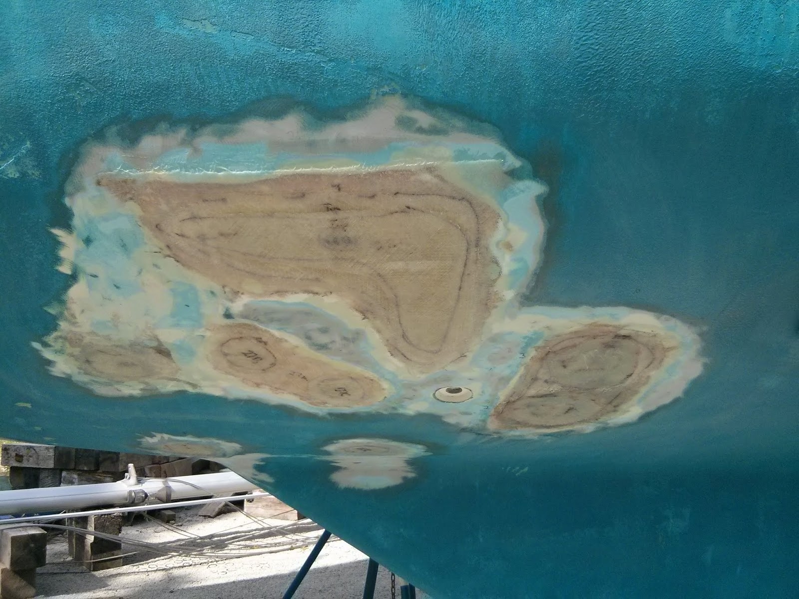
Our pre-purchase survey noted no hull damage or blisters, but of course that would be too good to be true.  We have discovered two areas of damage and 25 blisters.

Via casual inspections of the hull since Pilgrim’s arrival in Beaufort, I’ve notice a few areas that appeared as short cracks in the bottom paint.  Dis-coloration on the bottom paint around the cracks was indicative of moisture. 
Small cracks with discoloration due to moisture marked trouble on Pilgrim's hull.
Using an awl and a utility knife I picked open a couple of the cracks…
Opening the cracks with a knife revealed dry, brittle chopped strand mat (CSM)
None of them burst or squirted a stream of fluid as I have encountered with blisters on other vessels.  Rather the mat revealed appeared dry and brittle.  I suspect these are areas did not receive enough epoxy to wet out the mat in the original construction or they are poorly executed attempts at blister repairs by a previous owner.

To date I have discovered and ground out 25 such “blisters”.  In nearly every one, the compromised material was limited to the outer layers of chopped strand mat (CSM). I found no water intrusion into the woven roven cloth layers of the hull.  In the most severe cases water moved laterally between the CSM and Woven layers creating areas of delamination.
Starboard side aft of keel - larger area of delamination on left and grapefruit sized area on right.
In the image above the area to the left represents an area of delamination.  The smaller, grapefruit sized, area on the right is representative of the typical blister without delamination.

The greatest concentration of blisters is located on the starboard side under and forward of the head.
Portside forward of keel 
Up and right in the image above is a large area ground out due to hull damage.  This site is located under the head pan just forward of the counter top . The head sink drain thru-hull can be seen just below the damaged area.  I believe this damage is caused by the weight of the head pan resting on a narrow section of the interior of the hull.
Damaged hull directly below wall supporting head counter top.
In the image above, white, discolored fiberglass indicative of stress damage is present directly under and in line with the interior wall below the head counter top.   I believe additional tabbing added by the Morgan repair team and later by myself have remedied the cause of the stress.
Portside directly below the cockpit we found a poorly executed hull repair. 
The largest area of delamination was under a poorly completed hull repair on the portside below the cockpit.  I believe the crack is from improperly loading a jack stand.
The dark brown areas are sites where water is weeping out from under the CSM layer of the hull layup.  Pilgrim has been on the hard for six months 
The previous repair consisted of some polyester resin troweled into a “U” shaped notch.  This inadequate repair allowed water to seep into the surrounding fiberglass.  As with other areas on the hull once the water found its way through the chopped strand mat (CSM) it migrated latterly between the CSM and the woven roven cloth.
Port aft hull with large area of delamination and raw water thru hull (below jackstand) ground out.
Ultimately, to remove all the delaminated material required grinding out an “L” shaped area 32” X 32”.

After nearly ten days of exposure to dry weather and no signs of additional moisture from the hull, we have begun filling the damaged areas.
Small area on starboard side filled with two layers of 1708 cloth
 Using a marker, I numbered the sites on the hull that would require 1708 cloth patches.   Once the patches were cut we placed them in numbered ziplock bags to keep things organized.  The sites were numbered 1 – 32.  If a site required multiple layers then the patches were labled A,B,C, etc . The blistered areas required one to three layers of cloth.  The two damaged areas required four layers of cloth.  Filling the old thru-hulls required eight or more layers of cloth
We worked as a team to apply the new fiberglass cloth.   Anne mixed epoxy and wet out cloth.  I applied the cloth to the hull.   We filled some of the small areas and old thru-hull holes last week (See Previous Post: Replacing Thru-Hull Fittings & Seacocks – Part 1).
Large area on port side filled with up to 5 layers of 1708 cloth

Confident from last week’s success we tackled the large 32” X 32” area on Monday afternoon.  The damage required up to four layers and around 20 square feet of 1708 cloth.

Thursday, April 24, 2014

Replacing Thru-Hull Fittings and Seacocks - Part 1

Since Pilgrim's arrival we have extricated five thru-hull fittings and three thru-hull transducers.   I believe the five recessed thru-hull fittings were original to the vessel.  Two of the transducers just forward and starboard of the keel appear to be original.  The third transducer, a newer model, was located mid-ship just starboard of the keel.  

We plan to install a single thru-hull transducer in the forward most existing hole located just  forward and starboard of the keel.  This site is accessed through the panel just forward of the vee berth door.    We have yet to purchase a transducer, and will leave this hole unfilled until we confirm the  diameter of the new unit.

The arrival of our new thru-hull fittings and seacocks has inspired us to focus our energy on filling the old holes and installing the new hardware.
New Forespar Marelon thru-hull fittings (white) and seacocks (black)
The Forespar Marelon fittings and seacocks on C’est la Vie, installed in 1997, served us well and without issue.  The marelon negates the need to worry about grounding to prevent electrolysis.  Thus we are installing identical hardware on Pilgrim. 

In the head…
Exterior view of the original three recessed thru-hulls in the head.
We plan to use one of the existing ¾” holes in the head for the sink drain.  The head sink drain will be the only thru-hull fitting to remain in it’s original position.  Using an original placement requires a recessed thru hull fitting for this site.  All the new thru hull installations will be of the mushroom head variety.  We will install a new 1 ½” thru hull for the offshore black water pump out in the vicinity of the old 1 1/4" hole.   

In the galley…
Below the galley sinks.  We plan to cut away a bit more of the floor to install the new thru-hull directly below the sinks.
We plan to install a new 1 ½” thru-hull and sea cock for the sink drains.  The new thru-hull  will be more in line with the drains and closer to the keel.

In the wet locker opposite the galley sinks…
We plan to install a new ¾” thru-hull, seacock, and filter.  This fitting will serve as a raw water intake for the salt water food pump at the galley sinks and the salt water intake for the head.

Below the quarterberth deck…
The engine raw water thru-hull, seacock, and strainer will occupy the aft (top) section of the newly divided area below the quarterberth deck.
We plan to install a new 1 ½” thru-hull, seacock, and strainer, to serve as the engine raw water intake.  I decided to move the raw water intake to this location to provide easier access to seacock and strainer.  The original raw water intake was under the floor of the portside cockpit locker.

The interior areas around the existing thru-hull holes were ground down during previous projects.
the three existing holes remaining from the original head thru-hull fittings
The exterior required a visit from the 4” angle grinder with a 36 grit pad to prep it for filling the holes.
The aft two head thru-hull fittings ground down and ready to be filled with fiberglass cloth
Of course suiting up and venturing under the boat with the grinder in hand lead to the excavation of some blisters and poorly executed previous repairs , but I’ll save that for a future post.

Once all the holes were ready inside and out we added one layer of 1708 cloth to the interior.
One layer of 1708 cloth over the interior of the old galley thru-hull
We then moved outside, added a bit of thicken epoxy to the hole to avoid air bubbles, and filled the holes with between five and seven layers of 1708 cloth.  The number of layers varied depending on the thickness of the surrounding hull.
The exterior view of the old galley thru-hull
I discovered some debate as to the best method for laying up cloth to fill the old hole.  Ultimately I decided to start with the largest piece of fabric against the hull and work out to smaller pieces until reaching a relatively uniform thickness.  I believe stacking the wet cloth in this order makes it easier to avoid air bubbles trapped in the layup.
The exterior view of the old head thru-hulls
Next step will be to grind down the surplus material and fair the area back to the hull.

Sunday, April 20, 2014

Fabricating Locker Dividers that Match the Hull Shape

As part of our refit we are relocating the raw water intake & strainer.  Originally the through hull and strainer were located in on the port side under the cockpit locker.  We are moving them to the starboard side under the quarterberth deck. We believe the through hull valve and strainer will be more accessible on the starboard side.  We are also creating a new mount for the starter battery under the forward end of the quarterberth.

The original layout of the quaterberth deck and access panel.
To ensure no salt water from the strainer or through hull ever finds its way to the starter battery we are fabricating a divider in the locker that will be fiber glassed to the hull. 

Providing adequate egress to the work area and future relocation of the access panels necessitated removing the forward third of the quarterberth deck.

Forward third of the quarterberth deck cut away.
Transferring the location of the divider onto the arc of the hull took some creative measuring techniques.  The line drawn on the hull in the image above marks the position we wish to install the divider.

To create a template that matched the curve of the hull I used scrap lumber and hot glue.  The process began by clamping a 1X4 horizontally across the deck and in line with the future divider.  Then, using  1/8” plywood I glued three vertical strips down to the hull.

Creating a template using scrap wood, tin snips, hot glue, and clamps.
Using tin snips to trim the plywood, I created a piece that connected the three vertical strips near the surface on the hull.  I then attached on small pieces that contacted the hull at approximately 2 inch increments.   

The small pieces along the bottom make contact with the hull at a single point.
Once completed I removed  the template from Pilgrim and headed over to the shop.


In the shop I transferred the outline of the hot glued template to a piece of 1/8” plywood.


I connected the dots free hand with a marker.

With the outline transferred to the plywood, I used a bandsaw to cut out the template.

The 1/8” template made a couple trips back and forth between the bandsaw and the quaterberth to achieve a good fit.


Once pleased with the fit,  I transferred the outline of the 1/8” template to the ½” plywood that will serve as the divider.


The final piece fit precisely on the first attempt.
t
Test fitting the 1/2" plywood Divider
The aft (upper in the image above) space will house the raw water intake.  The forward space will house the starter battery and  serve as storage for a tool box.

Using 1/8" plywood to experiment with the location of locker dividers.
Time to create templates for dividing the space up again… tool box on left. battery on right.