We are
expanding the original electrical panel aft to effectively double its size.
 |
| Test fitting the enlarged frame for nav station over cardboard template of terminal block and bus bars layout. |
We designed
the panel to have two hinged sections.
Since the forward section will be easier to see and interact with while
sitting working at the nav station this section will house instruments, alarms,
solar charge controller, etc. The aft
section will house the new electrical panel.
The forward
section took a bit of trial and error to layout. Knowing that we will inevitably wish to add additional
devices to the panel we choose to squeeze all the current devices tightly together
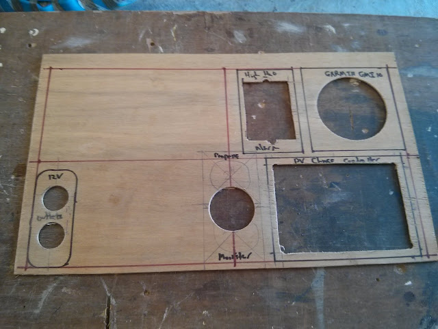
and leave some empty space for future expansion. Once we agreed on the layout, I transferred the design to a piece of 1/8” luan plywood.
 |
| Creating a template of the new instrument panel. |
 |
| Actually cutting out the holes in the template revealed a few errors. |
Creating the
template allowed me to test fit the devices prior to making the first cut on
the actual panel. This proved fortuitous
as the hole for the battery monitor was slightly undersized and the two holes
for the 12V charging outlets we slight too far apart. Better to make these discoveries on a piece
of luan than the finished panel. Once
the corrections were made, I transferred the pattern to the panel and cut out
the appropriate holes.
 |
| Cut outs completed on new panel. |
Installing
the actual electronics in the panel simple required drilling a few pilot holes
for mounting screws.
 |
| Face on new panel with devices installed. |
The devices
listed clockwise from top are… High Water Alarm, Garmin GMI10 Multi-FunctionDisplay, Blue Sky Solar Charge Controller 2000E, Victron Battery Monitor, and West
Marine Double 12V Outlet.
The backside
of GMI10 and the Victron Battery Monitor appear fairly well protected. The high water alarm is housed in a plastic
outlet box. The back of the Blue Sky
Charge Controller consists of an exposed printed circuit board.
 |
| Backside of panel with starboard sides of charge controller cover installed. |
Rather the
take our chances on leaving it exposed, I fabricated a cover using ¾” starboard
on 3 sides.
 |
| Lower edge of charge controller containing the terminal block remains open for wires. |
Then capped
with a ¼” lexan cover. The devices
terminal block is located along the lower edge so this side was left open.
See our Navigation Station Re-Fit Photo Album for images and notes current
progress.

No comments:
Post a Comment