SV Pilgrim - 1979 Morgan 382 - Homeport: Beaufort, NC

Sunday, August 23, 2015

New Companionway Drop Boards

Rare is the boat project that can be completed in a single afternoon. 

Pilgrim's tired, teak drop boards.
Pilgrim arrived in Beaufort with three teak companionway drop boards.  The existing teak drop boards are both too thin, between ½” and 5/8”, and too short.  Due to the inadequate size, the boards would bind up unless extreme caution was employed when removing or installing them.

The solution?  Two new ¾” thick King Starboard drop boards.  Since the Starboard does not require painting or varnishing, the project fit neatly into a couple hours…
  • Lay out the proper dimensions.
  • Rough cut the Starboard with a circular saw.
  • Using a router, create a rabbit joint between the upper and lower boards.  Set up the joint to shunt water outside the boat.
  • Using flush trim and round over bits in the router, finish the edges of the boards.
  • Install the hasp.


Pilgrim's new Starboard drop boards.

The new boards slide easily in and out of position.  Unlike the top of the slider or the exterior companionway step pictured above, the new drop boards will never require refinishing. 

We plan to replace all the exterior teak in the image above… in due time.


Sunday, August 16, 2015

Painting Ice Box and Engine Beds

We chose to use Alexseal Epoxy Primer and Alexseal Premium Topcoat for the engine compartment beds and surrounding  hull.  Why the Alexseal? 
  • We used the same system on the interior of the new ice box and are very pleased with the finished product. 
  • The Alexseal system will create a durable, glossy, easily cleaned surface. These attributes are desirable in both the engine compartment and the ice box.
  • We need to paint the seam along the aft wall of the ice box. Using the same paint will allow us to tackle both the engine compartment and the ice box project at the same time.

I know it’s been awhile since we mentioned the ice box rebuild (Ice Box Rebuild Photo Album).   We completed the fabrication of the new ice box last spring.  Painting the seam along the aft interior wall remained unfinished.

Seam along the aft wall of the ice box is prepped and ready for primer.

Building up the Alexseal epoxy primer "wet on wet" creates a stronger bond between the layers and eliminates sanding between coats.  How to reach the aft end of the compartment without marring the still tacky primer? 

The lower engine compartment ready for primer.

I experimented with painting the aft area via the cockpit locker and quarterberth access panels, but this proved too awkward.  My solution... leave the tops of the engine beds for another round of painting and place a piece of ¾” plywood across the beds.  This created a stable, albeit slightly angled, platform above the curing primer.

3/4" Plywood painting platform atop the engine beds.

Using this system I applied four coats of primer…

Four coats of epoxy primer complete.

The primer must cure for a minimum of 3 hours between coats.  The four coats of primer when on over a two day time span. The primer must be allowed to cure for 24 hours and then sanded before the top coat application. 
   
When using a brush to apply top coats a 24 hour cure time followed by sanding is required between coats.  The sanding generates unwanted dust so the area must be cleaned and wiped down in prep for the next coat.  Applying the two top coats occurred over a four day time span.

The finished product... a blank canvas on which to begin the engine install.

The top of the engine beds still require some primer and paint.

The top of the engine beds will be painted along with the interior face of the ice box lid.  The ice box lid is still under construction, but the ice box interior is looking good.

The interior of the new ice box is ready for divider & shelving installation.


The next step on the ice box is to install the vertical divider and the shelves.

Saturday, August 8, 2015

Painting Engine Beds and Surrounding Hull - Part 1

Somewhere in Pilgrim’s past a previous owner did a poor job of applying oil based paint to the engine beds and a portion of the surrounding hull.  Removing the paint with a heat gun and paint scraper would be the best case scenario.  Since we are discussing good old boat project the best case scenario failed.  


Masking the engine compartment in prep for grinding after failing to remove the paint with heat ans a scraper.

The two somewhat bare areas between the beds in the image above mark my attempts to heat and scrape. The effort resulted in gouges; strands of woven-roven mat tearing away from the hull; and paint left in the low spots. 

What next? 

Mask every opening, see images above and below.

draping plastic sheeting across the engine compartment access in an effort to contain the dust.

Suit up.
 
Plug in the grinder and shop vac.

Crawl under the plastic and into the engine compartment with the power tools.   

Generate vast amounts of dust while sweating out gallons of fluid.

On round one I succumb to the heat after sanding the aft half of the area.

The aft portion of the engine compartment hull completed in round one.

For round two, the next day, I rigged a box fan to pull air and dust out via the locker under the helm seat.  By the end of round two all the grinder accessible areas were completed. Everything the grinder was unable to reach… outboard of the beds and the narrow area along the centerline… required hand sanding.

Round three, four, five... multiple 60 to 90 minute sessions of hand sanding with 40 grit paper stretched out over a couple days.  The initial session taught me to wear leather gloves when driving 40 grit sandpaper.   

Majority of sanding completed.

The grinding and sanding revealed a couple areas requiring some minor fiberglass repair.

De-laminated area along forward, starboard bed removed.
Crack in fiberglass mat along forward, port engine bed.
I was able to repair these issues in a single session of epoxy work

Few layers of 1708 cloth covered with a single layer of finish cloth.

While working the area, I noticed the irregular texture and pitch of the center line caused water to pool in a few areas.  No time like the present to address this issue.

Fairing the center line to allow for proper water drainage.

Using tropical hardener to allow for a thick lay up in the summer heat, I mixed up a batch of epoxy thickened to a honey consistency.   This mixture was poured into the center seam near the stern.  With only some minor coaxing from a spreader, I allowed the thick fluid to find its own level.  Once the epoxy began to kick, I laid a single layer of finish cloth across the top.

Once all the repair work was completed the area receive a thorough cleaning with Tri-Sodium Phosphate (TSP).

Engine beds and surrounding hull ready for the first coat of primer.

The area is now masked and ready for primer.

See our Repowering Photo Album for images and notes current progress.


Monday, August 3, 2015

Refinishing the Engine Compartment Overhead & Walls

The best illustration I could find of the existing paint in the engine compartment is a dated image (old drain manifold, hole from original engine raw water intake on port, refrigeration lines feed into ice box, and no bulkhead separating the engine compartment from the cockpit locker).

Old image of Pilgrim's engine compartment that illustrates the need for repainting the area.

The image does do a good job of illustrating the dingy, tired paint on the walls; a lack of paint overhead, and the poor quality oil based paint applied to only a portion of the hull. 

We decided to take a top down approach to painting the engine compartment.  We began with the overhead and vertical side walls.  Most of the surfaces required only minor prep work… TSP wash down followed by two rinses with fresh water.  The overhead was previously lined with decaying soundproofing material.  The sound proofing was easily removed. The steel sound proofing mounting tabs were epoxied to the overhead.  The epoxied tabs quickly succumb to a hammer and old chisel.   The forward, interior of the cockpit foot well (see brown area in image below) was also covered with sound proofing material.  Unlike the overhead this section of sound proofing was glued to the boat.  The heavy application of contact cement proved very stubborn.

State of Pilgrim's engine compartment prior painting.

Rather than engaging in a prolonged battle to excise the old glue, we fabricated a plywood panel for the area.  Once again we reused sections of the original salon aluminum angle for mounting the plywood panel.  The plywood has the added benefit of allowing us to easily mount wiring, electrical components, hoses, etc.

Overhead and side walls of engine compartment painted.

We plan to install new sound proofing material on the two port access panels, the starboard access panel, the forward access panel, and the overhead.  The sound proofing will be added once all the other dust producing projects are completed.


See our Repowering Photo Album for images and notes current progress.

Saturday, August 1, 2015

Back to Producing Dust

Our recent progress with installing electrical and plumbing components really inspires me to continue work on those systems, but some items remaining on our project list require grinding inside the hull.  Grinding inside generates awful gelcoat and fiberglass dust.  Despite our best efforts at masking the fine dust always finds its way into the rest of the boat.   Thus, we really need to complete all the projects that require grinding inside the hull, prior to installing additional electrical, plumbing, or mechanical parts.

What is on the get the grinding done list?
  • Repair some detached fiberglass mat on the engine beds.
  • Paint the engine compartment and beds.
  • Relocate engine exhaust thru-hull.
  • Tabbing modifications and repairs to area around steering quadrant.
  • Install mounting platform for new, below decks autopilot.
  • Paint locker under helm seat.

We plan to start with the painting the engine compartment.

Thus far in our refit we have used the forward cabin for storage of cushions.  Other than removing a depth transducer we have completed no interior work in the forward cabin or anchor locker.  There are dust generating, messy projects forward (anchor locker modifications, tabbing between bulkheads and deck, etc.).  Since this area is relatively easy to seal off from the aft portion of the interior, we plan to address this area at a later date.

With respirator and grinder in hand, I’m off to generate some dust.


Friday, July 31, 2015

Nav Station Instruments and Electrical Panel Façade – Part 2

Installing panels in the frame required creative hinge work.

Test fitting new nav station electrical and instrument panels.

To provide the most ergonomic access to the backside of the panel we chose to hinge the aft, electrical panel section along the forward, vertical side.  Hinging the panel to swing forward provides easy access to the panel while sitting at the nav station.   It also places additional stress on the hinge.  To accommodate the additional forces I chose to surface mount the hinge. Then thru-bolted machine screws to attach the hinge to the panel. 

The BassPanel contains 20 D/C breakers, 8 A/C breakers, an A/C reverse polarity indicator, analogue load gauges for both D/C & A/C systems, and analogue voltage gauges for both D/C & A/C systems.

Being uncertain what devices may be added to the forward panel in the future, I felt the best option was to place the hinge along the lower, horizontal edge of the panel.    Thus panel swings down and rests atop the nav station desk.  This action provides access to the back side of the panel while sitting at the nav station.  Accessing the items mounted on the hull outboard of the panel can be achieved by kneeling on the nav station bench seat.

The forward, instrument panel hinges down.  The aft, electrical panel hinges forward.

I recessed the foreword panel slightly by installing the hinge to the vertical face of the panel and the horizontal edge of the frame.  This provides additional clearance between devices installed in the panel and the hinged nav station desk top that swings upward when opened.

The final install will include trim along the top and an arm rest / storage below the aft section.

Currently panel is simply slid into place for test fitting.  For the final installation we will secure it with screws and add trim along the top edge.  We also plan to build an arm rest / storage below the electrical (aft) panel.  The arm rest will hide the wire runs entering the panel from below.


See our Navigation Station Re-Fit Photo Album for images and notes current progress.

Sunday, July 26, 2015

Nav Station Instruments and Electrical Panel Façade

We are expanding the original electrical panel aft to effectively double its size.

Test fitting the enlarged frame for nav station over cardboard template of terminal block and bus bars layout.

We designed the panel to have two hinged sections.  Since the forward section will be easier to see and interact with while sitting working at the nav station this section will house instruments, alarms, solar charge controller, etc.  The aft section will house the new electrical panel.

The forward section took a bit of trial and error to layout.  Knowing that we will inevitably wish to add additional devices to the panel we choose to squeeze all the current devices tightly together and leave some empty space for future expansion.  Once we agreed on the layout, I transferred the design to a piece of 1/8” luan plywood.

Creating a template of the new instrument panel.

Actually cutting out the holes in the template revealed a few errors.

Creating the template allowed me to test fit the devices prior to making the first cut on the actual panel.   This proved fortuitous as the hole for the battery monitor was slightly undersized and the two holes for the 12V charging outlets we slight too far apart.  Better to make these discoveries on a piece of luan than the finished panel.  Once the corrections were made, I transferred the pattern to the panel and cut out the appropriate holes.

Cut outs completed on new panel.

Installing the actual electronics in the panel simple required drilling a few pilot holes for mounting screws.

Face on new panel with devices installed.

The devices listed clockwise from top are… High Water Alarm, Garmin GMI10 Multi-FunctionDisplay, Blue Sky Solar Charge Controller 2000E, Victron Battery Monitor, and West Marine Double 12V Outlet.

The backside of GMI10 and the Victron Battery Monitor appear fairly well protected.  The high water alarm is housed in a plastic outlet box.  The back of the Blue Sky Charge Controller consists of an exposed printed circuit board.

Backside of panel with starboard sides of charge controller cover installed.

Rather the take our chances on leaving it exposed, I fabricated a cover using ¾” starboard on 3 sides.

Lower edge of charge controller containing the terminal block remains open for wires.

Then capped with a ¼” lexan cover.  The devices terminal block is located along the lower edge so this side was left open.


See our Navigation Station Re-Fit Photo Album for images and notes current progress.

Thursday, July 23, 2015

Prep Work for Nav Station Electrical Panel Upgrades

When we purchased Pilgrim it came equipped with the original 1979 Morgan Yachts electrical panel.

Original 1979 Morgan Yachts Electrical Panel.  We sold this panel to another Morgan Owner.

While still fully functional, this panel lacked the appropriate number of DC breakers to accommodate the system upgrades we have planned.  Due to the large analog meters and double pole AC breakers the panel also has a large footprint relative to the number of breakers.

Most of the original wiring associated with the panel was shoe horned into a tiny area below the interior of the nav station storage.  Since we plan to expand the number of circuits, we will also need more space to mount the “back end” (terminal blocks, bus bars, etc.) of the electrical system.  Our plan is to install plywood panels along the hull out board of the nav station.  These panels will provide a large vertical surface area for mounting various components of the electrical system.

First step of the process is to identify the location and orientation of the frames.  Frames are typically wood strips secured to the hull, typically with epoxy, that provide a mounting surface on to which interior structures (i.e. cabinetry, ceiling panels, wall coverings, etc.) can be mechanically fastened. 

X marks the areas need to be ground down to bare fiberglass.

The hull outboard of the nav station has little curvature and our access is limited thus orienting the four frames horizontally worked better in this location.  The lower, forward frame location is eclipsed by the nav station desk in most of the included images.

We plan to epoxy the frames to the hull so the next step is to grind the area under the frames down to bare fiberglass.  Time to suit up and make some dust…yuck.

Grinding complete.  Now where is the shop vac?

We have some of the original frames Morgan used for the headliner as spares so we recycled them for this project.  Thickened epoxy was then used to bond the frames to the hull.

Recycling unused headliner frames for the new electrical panel.

Once the frames were cured and permanently in place, we added a single layer of 3/16” reflectix insulation along the hull.

On a whim we added a layer of 3/16" thick reflectix insulation along the hull.

A few weeks ago we used some cardboard templates to begin laying out the electrical system.
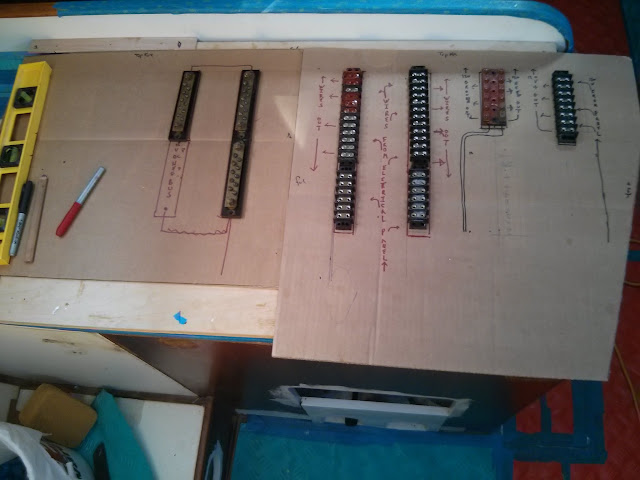
Cardboard templates of the new panels are used for experimenting with the electrical system layout.
We used 3/8” plywood pre-coated with white Formica to create the panels.  These are attached to the frames using counter sink, flat head screws.

Ahh... a blank canvas for creating the new electrical system.

We now have plenty of real estate for mounting the new electrical system.

We drilled a few large diameter holes far outboard in the nav station seat.  These will be used for future wire runs.  Our plan is to cover the wire runs with a arm rest / storage cubby once the electrical system is in place.


See our Navigation Station Re-Fit Photo Album for images and notes current progress.