SV Pilgrim - 1979 Morgan 382 - Homeport: Beaufort, NC
Showing posts with label Tabbing. Show all posts

Thursday, June 4, 2015

New Shelf for the Cockpit Locker

Adding a shelf outboard along the hull in the cockpit locker will provide some additional storage possibilities and a platform on which to mount the refrigeration compressor.  

The fore end of the shelf will rest upon the top of the new bulkhead. 
Test fit of new 1/2" plywood shelf in cockpit locker.

Tabbing a ½” plywood panel to the upper, aft interior of the cockpit locker (upper, left in image above) allowed me to easily attach a bracket to support the aft end of the shelf.

The shelf will be tabbed to the hull along the outboard side thus another round of grinding to expose the fiberglass hull.

Pile of gel-coat and fiberglass dust after grinding to expose bare fiberglass. YUCK!

I am eager to be done with grinding fiberglass inside the boat.  It creates a huge mess and fine dust spreads throughout the interior.

We created the new shelf using the 1/2” prefinished birch plywood.  Unfortunately the nice finished surface must be ground off in the areas receiving tabbing. 

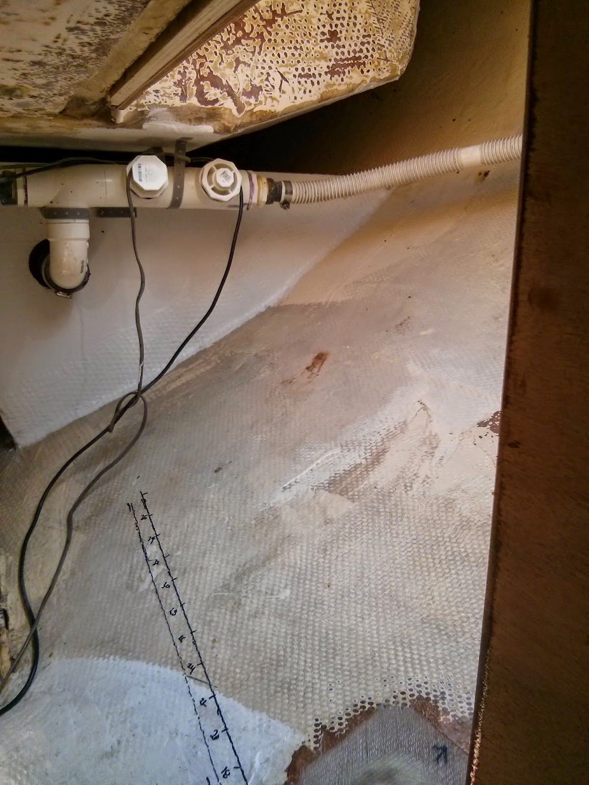
48" run of 1708 cloth tabbing between the hull and the new cockpit shelf.
For people familiar with the M382, yes, this photo was taken from below the helm seat.

We installed a 48” X 6” strip of 1708 cloth .  The tabbing stiffens and strengthens the shelf significantly. 

Next, we applied two coats of primer and two coats of paint to the shelf and the upper sections of the cockpit locker.

Ahh... the satisfaction of fresh, unmarred paint.

Our plan is to mount the refrigerator compressor near the aft end of the shelf.  Then install one maybe two vents in the cockpit side wall to provide the unit with fresh air. The forward end of the shelf will store cleaning, maintenance, misc supplies in plastic bins.  To keep the plastic bins in place while the boat heels we added a tall fiddle along open face of the shelf.

Teak fiddle installed on the shelf and deck drain hose secured to underside of shelf.

Next up is installing the engine access panels and plumbing the lower and middle bilge pump discharge hoses to the drain manifold.


More images and notes from this on-going project are available in the Cockpit Locker Refit Photo Album

Monday, May 25, 2015

Cockpit Locker Refit

Yes we continue to make progress on the ice box. The aft panel perimeter is on its third and hopefully final round of fairing.

Much more exciting changes are happening in the cockpit locker.  We just created a new photo album devoted to the project – Cockpit Locker Refit.  We will continue to add new photos to the album as the project continues.

When we took possession of Pilgrim the vertical panel dividing the engine compartment and the cockpit locker was held in place by four bolts at the top and wood screws into the locker floor at the bottom.  The locker floor tabbing had failed due to poor construction techniques at the factory (the tabbing was bonded to gel coat on the hull interior.)  Thus the entire assembly, hanging off the bolts atop, was able to swing a couple inches into the engine compartment.

Once the tabbing cured on the new forward bulkhead we began work on fabricating a new panel to divide the engine compartment and the cockpit locker.

The effort began by using some scrap 1” X 2” to experiment with the placement and size of the panel.

Experimenting with the size and position of the panel.

Once satisfied with the concept we marked out the location of the panel along the hull.

The desired location marked on the hull and divided into two inch segments.

Dropping and measuring a plumb line from the panel above at two inch increments gave us the data we needed to transfer the curve of the hull to the new plywood divider.

Transferring measurements taken inside the boat to the 1/2" plywood. 

The effort produced a good fit.

Test fitting the new panel... we are pleased with the results.

Next we cut a large opening in the center of the panel.  This opening will provide engine access via to removable hatches.

Clamping the hatch frames in place.

After creating a frame to hold the hatches in place we tabbed the new panel in place along the hull.

Tabbing, directly to bare fiberglass, on both sides of the new panel anchor it to the hull.

And to the vertical side wall of the cockpit at the top.

Single layer of tabbing and three thru bolts secures the top of the new panel. 

We installed new bolts in three of the four original holes across the top.  This made the installation easier and adds an additional measure of structural integrity to the assembly.

With the vertical panel in place we are able to begin laying out the new cockpit floor and other pieces of new cockpit locker cabinetry.

Test fit of locker floor and template for small partial bulkhead aft.


More images and notes from this on-going project are available in the Cockpit Locker Refit Photo Album.

Thursday, May 21, 2015

New Bulkhead In the Cockpit Locker

 The template of the cockpit locker hull I created a few months ago (here is a link - January 18, 2015) has proven very helpful.  I utilized it for shaping the ice box insulation and the new plywood bulkhead.

Attaching scrap 1" X 2" to template  to attain the proper fit for the new  bulkhead.

After building out the insulation, the template fit more accurately along the hull than along the top or vertical side.  I clamped and screwed pieces of scrap 1” X 2” lumber to the plywood template to accurately capture the outside dimensions of the new bulkhead.

Tracing the template onto the sheet of marine plywood.

Once satisfied with the fit, I clamped the template atop the plywood and marked out the new bulkhead.

I am amazed at what boat owners and contractors will leave behind or toss in boat yard dumpsters. We have used a lot of recycled and reclaimed materials in our refit, but, mission critical components (thru-hull fittings, standing rigging, backing plates, etc.)  require total confidence in the materials.  New, marine plywood for bulkheads definitely falls onto our required materials list.

Some projects require absolute confidence in the materials.

We anticipate one 4’ X 8’ sheet will allow us to complete all the new structural components of the cockpit locker cabinetry.   We will be posting more information on the changes to the cockpit locker in the near future.

Installing new bulkhead.

The new bulkhead fit precisely on the initial cut.  The top and side panels, from the same sheet of marine plywood were quick to follow.

Looking down thru cockpit locker access at new bulkhead assembly. 

Initially, I installed the three pieces with fillets of epoxy and #8 X 1” countersunk wood screws.  Once the epoxy fillets cured, I cut and test fit 1708 cloth tabbing.

Test fitting layers of 1708 cloth tabbing.

Wetting out and installing large sections of tabbing in cramped quarters is definitely a two person job. Anne joined in the fun.

Anne preparing to lay up tabbing on new bulkhead.

Structurally the bulkhead is now complete.

Two to three layers of tabbing on new bulkhead.

We got big plans for the rest of the cockpit locker.  Oh yeah and an ice box to finish up.


More images and notes from this on-going project are available in the Ice Box Rebuild Photo Album

Saturday, January 17, 2015

Watertight Plumbing Conduit Under the Ice Box

Rainy, cool weather has delayed dropping Pilgrim’s rudder and forced me inside.  Fortunately a small portable heater maintains a comfortable working temperature inside the boat.

Like the original construction we plan to have multiple bilge pump discharge hoses, a propane line, and likely a couple electrical wires running under the ice box.  Now that we have fiber glassed close the gaps under the wall between ice box and the engine, any possible leaks from the hoses or spills in the cockpit locker could collect under the ice box.  My initial solution was to drill a couple limber (drain) holes along the base of the wall separating the engine and the ice box.  This solution had the downside of again allowing hot air from the engine access to the underside of the ice box.   A more elegant solution would be to create a water tight conduit between the cockpit locker and area under the stove.

Initially I looked for a large diameter PVC or fiberglass pipe to cut in half and glass down to the hull.  This search proved fruitless, but in my scrounging around I discovered some scrap pieces of 1” thick fiberglass paneling with a foam core.  Ok… the conduit will be square.
Creating templates for the conduit side walls.

The conduit began as so many custom fabrications do… by using luan plywood strips and a glue gun to create a template.  The templates of the 3” tall side walls were then transferred to the fiberglass panel.
Transferring the side wall template to the 1" thick fiberglass panel.

The more I worked with the 1” paneling the more I realize how ideal it is for this application.  The foam will add to the insulation. The strength of this stuff when laid up with heavy mat will add structurally to the hull.
Ready to tab side walls to hull and adjacent bulkheads.

After test fitting the side walls and cutting 1708 cloth tabbing, I glassed them down.  To minimize the risk of chafing hoses, I added a nice fillet along the inside corners.
Test fitting the top section.

Once the side walls cured, I was able to lay out the top section.

Beveling  the long edges along the top to allow the fiberglass cloth to smoothly lie over the corner.  After filling any gaps with thickened epoxy, I laid a single piece of 1708 cloth across the top ad down the sides.
 
Fiberglass work on conduit complete.
Once all the epoxy had cured, I sanded down any rough edges.

Conduit complete.

The outside dimensions of the conduit look large, but it incorporates one inch of foam insulation.


More images and notes from this on-going project as available in the Ice Box Rebuild Photo Album

Tuesday, December 30, 2014

Installing New Tabbing In the Ice Box Compartment


Prior to cutting any cloth for tabbing, we filled the gap between the two aft bulkheads with expanding foam.
Adding expanding foam between the two aft bulkheads.

Next we filled the voids under the aft bulkhead, mid-ship panel, and forward panel with expanding foam.
Adding foam under the aft bulkhead, mid-ship panel, and forward panel.

After cutting away the excess foam, we dry fit sections of 1708 cloth tabbing  along the various surfaces.
Dry fitting 1708 cloth between the hull and vertical panels in the ice box compartment.

The forward and mid-ship panels have one layer of cloth.   The cut out in the fore and aft bulkheads will allow the ice box drain, bilge pump discharge hoses, and the propane line for the stove to pass under the ice box.
Multiple layers of cloth on the double bulkhead aft.

We plan to capitalize on the discovery of the double bulkhead by laminating the two ½” bulkheads together to form a  single stout rib along the hull.  The achieve the additional strength this area received two to three layers of cloth.

Anne suited up for wetting out fiberglass cloth.

Wetting out and laying up large sections of fiberglass is always a team effort.
 
Looking forward from the cockpit locker at the new tabbing.
Looking down through the ice box lid at the heavy lay-up over the double bulkhead.

Another sign of Morgan’s hasty construction is the lack of bulkhead on the inside of the cockpit combings.   
Morgan did not extend the bulkhead between the cockpit locker and the galley did into the inside of the cockpit combing.

While we were in the neighborhood we filled the opening  at the top of the bulkhead between the cockpit locker  and the galley with a ½” The plywood insert .  We also added tabbing between the bulkhead and the underside of the deck.  Our additions should add strength to the hull and deck. 
Plywood insert extends bulkhead.  Tabbing bonds bulkhead to deck and combing.

Ultimately we plan to re-mount the Alder-Barbour condenser unit in this vicinity along with a vent into the galley for circulating air around the condenser.   

TO BE CONTINUED…


Here is a link to additional images and notes – Ice Box Rebuild Photo Album

Monday, December 29, 2014

Dissecting the Ice Box Reveals Morgan Construction Shortcomings

Here is a link to part one – Removing the Original Ice Box

I expected to unveil the cause of the leaking drain that initiated the ice box rebuild, I did not anticipate to discover…
Exterior of ice box drain fitting... and yes my foot is resting on the starboard engine bed in the background.
The fitting between the ice box and the drain hose was a 90⁰ hose barb.  Standard fare on the discharge end – a hose held in place with a stainless hose clamp – all good here.  At the ice box end - the hose was set in the box via a coat of epoxy painted atop the insulating foam.

The interior of the ice box drain fitting.  The flat surface was pressed against the exterior of the ice box.

The end of the hose barb was cut flush with the wall of the box.  That is it.  No mushroom head fitting.  No threads tapped into the box.  No caulking.  I have to believe this fitting has leaked since hull #115 rolled out of the production shed.  The mold in the insulation surrounding the drain fitting serves as additional evidence of a 35 year old leak.

Once all the ice box pieces were excavated and the last of the insulation crystals sucked into the shop vac, I marveled at a complete lack of tabbing between the hull and any of the surrounding cabinetry.
Looking forward through the ice box compartment at the unsupported 1/2" plywood wall below the galley counter top.

The wall forward of the ice box that forms the face below the counter top in the galley is unsupported for all but the lowest six inches.  The last six inches of the vertical panel (closest to the companionway) rests atop the cabin sole but is not directly fastened to the sole.  I cut the five inch circular hole at the lower right during my early attempts to replace/repair the ice box drain.  I will fill it later in the re-build.
Looking through the lid of the ice box at the unsupported base of the mid-ship, vertical wall that divides the ice box from the engine compartment.

The wall separating the ice box from the engine compartment also lacks tabbing to the hull and is unsupported along its entire length.    This opening allows hot air from the engine compartment direct access to the poorly insulated underside of the ice box – ridiculous!  The black mold in the image above is the remnants of the colony growing around the leaking ice box drain.

Time to purchase more 1708 cloth… TO BE CONTINUED.

Here is a link to additional images and notes – Ice Box Rebuild Photo Album


Thursday, September 4, 2014

Paint in Lieu of Headliner - The Port Side Story

Over the past few days painting the interior of the side decks in lieu of the headliner has migrated to the port salon and back into the galley.

The effort began with the removal of the cap shroud chainplate from the bulkhead
Port chain plates - Fore ground: aft lower tang.  Background: Cap shroud chainplate removed from bulkhead.

New we removed the aft lower chainplate …not so fast…  When we began to remove the lower, interior tang portion of aft chain plate I noticed  the surrounding deck sink by  1/8” to 3/16”.  The bulkheads and the cabinets along the port side neither touch nor are tabbed to the deck above.  It appears the two chainplates support the side deck. 

My solution…  Add sections of tabbing between the bulkhead and the underside of the deck to each side of the cap shroud chainplate.  Plus, add a long strip of tabbing along the entire length of the joint between the top of the port salon cabinetry and the underside of the deck.   To prep for the new tabbing I ground down the surfaces, added a series of #8 counter sink screws to the veneer along the bulkhead, and masked off the surrounding area to minimize the mess.
Ready to install new tabbing.  The tang for the aft lower was left in place to support the deck at the proper height.
Masking over the entire face of the cabinets proved to be a worthy endeavor as the long strip above the cabinets was tricky to install. 
A section of 1708 cloth applied on either side of cap shroud chainplate and 6" wide two strips of lighter cloth run the length of the cabinet face.
The new tabbing successfully supported the side deck with both chainplates removed. 

While set up to work with epoxy in the salon, I also filled holes from old fixtures and faired in some gouged areas along the forward salon bulkhead.
Taped off sections of bulkhead in preparation for epoxy filler

Sanding down epoxy filler - a messy job in the cabin.

prep work complete - taped and ready for the first coat of primer.
 90% of successful paint jobs is the prep work.   We applied two coats of primer and two coats of paint.  Below are the results…

Port salon bulkhead freshly painted.
Looking aft along port side of salon.  Note new tabbing between underside of deck and masked cabinet face.
Looking aft along port side of salon after painting.  Plan to install trim along both sides painted surface.
Interior of side decks in galley ready for the first coat of primer.
Fresh paint in galley.  Plan to add a section of trim between the painted surface and the cabinet face.

Looking forward from galley at newly painted bulkheads.

For more images and notes about work in the salon check out our - Salon Refit Photo Album.

For more images and notes about work in the galley check out our - Galley Refit Photo Album.

I still plan to pen a post sharing our experiences removing, servicing, and re-bedding the chainplates - stay tuned.