When we
purchased Pilgrim it came equipped with the original 1979 Morgan Yachts
electrical panel.
 |
| Original 1979 Morgan Yachts Electrical Panel. We sold this panel to another Morgan Owner. |
While still
fully functional, this panel lacked the appropriate number of DC breakers to
accommodate the system upgrades we have planned. Due to the large analog meters and double
pole AC breakers the panel also has a large footprint relative to the number of
breakers.
Most of the
original wiring associated with the panel was shoe horned into a tiny area
below the interior of the nav station storage.
Since we plan to expand the number of circuits, we will also need more
space to mount the “back end” (terminal blocks, bus bars, etc.) of the
electrical system. Our plan is to
install plywood panels along the hull out board of the nav station. These panels will provide a large vertical
surface area for mounting various components of the electrical system.
First step
of the process is to identify the location and orientation of the frames. Frames are typically wood strips secured to
the hull, typically with epoxy, that provide a mounting surface on to which
interior structures (i.e. cabinetry, ceiling panels, wall coverings, etc.) can
be mechanically fastened.
 |
| X marks the areas need to be ground down to bare fiberglass. |
The hull
outboard of the nav station has little curvature and our access is limited thus
orienting the four frames horizontally worked better in this location. The lower, forward frame location is eclipsed
by the nav station desk in most of the included images.
We plan to
epoxy the frames to the hull so the next step is to grind the area under the
frames down to bare fiberglass. Time to
suit up and make some dust…yuck.
 |
| Grinding complete. Now where is the shop vac? |
We have some
of the original frames Morgan used for the headliner as spares so we recycled
them for this project. Thickened epoxy
was then used to bond the frames to the hull.
 |
| Recycling unused headliner frames for the new electrical panel. |
Once the
frames were cured and permanently in place, we added a single layer of 3/16”
reflectix insulation along the hull.
 |
| On a whim we added a layer of 3/16" thick reflectix insulation along the hull. |
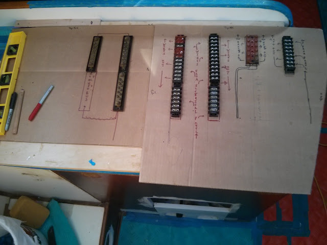
A few weeks
ago we used some cardboard templates to begin laying out the electrical system.
 |
| Cardboard templates of the new panels are used for experimenting with the electrical system layout. |
We used 3/8” plywood
pre-coated with white Formica to create the panels. These are attached to the frames using counter sink, flat head screws.
 |
| Ahh... a blank canvas for creating the new electrical system. |
We now have
plenty of real estate for mounting the new electrical system.
We drilled a
few large diameter holes far outboard in the nav station seat. These will be used for future wire runs. Our plan is to cover the wire runs with a arm
rest / storage cubby once the electrical system is in place.
See our Navigation Station Re-Fit Photo Album for images and notes current
progress.

No comments:
Post a Comment