SV Pilgrim - 1979 Morgan 382 - Homeport: Beaufort, NC

Sunday, April 26, 2015

Fillets and Fairing for the Ice Box

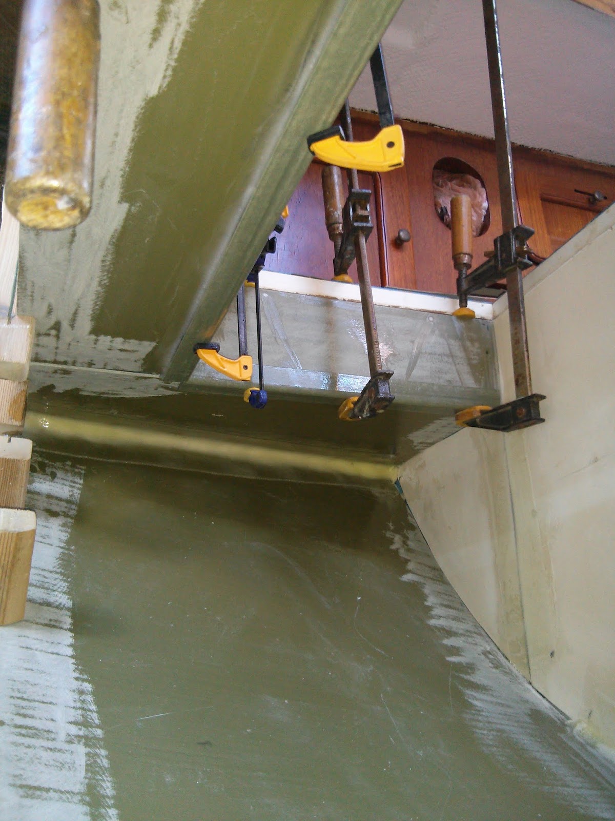
Once in place all the inside corners of the ice box were bonded together by laying a 4” wide strip of 6 oz fiberglass cloth atop a large fillet of epoxy thickened with cabosil (West 406 filler.)
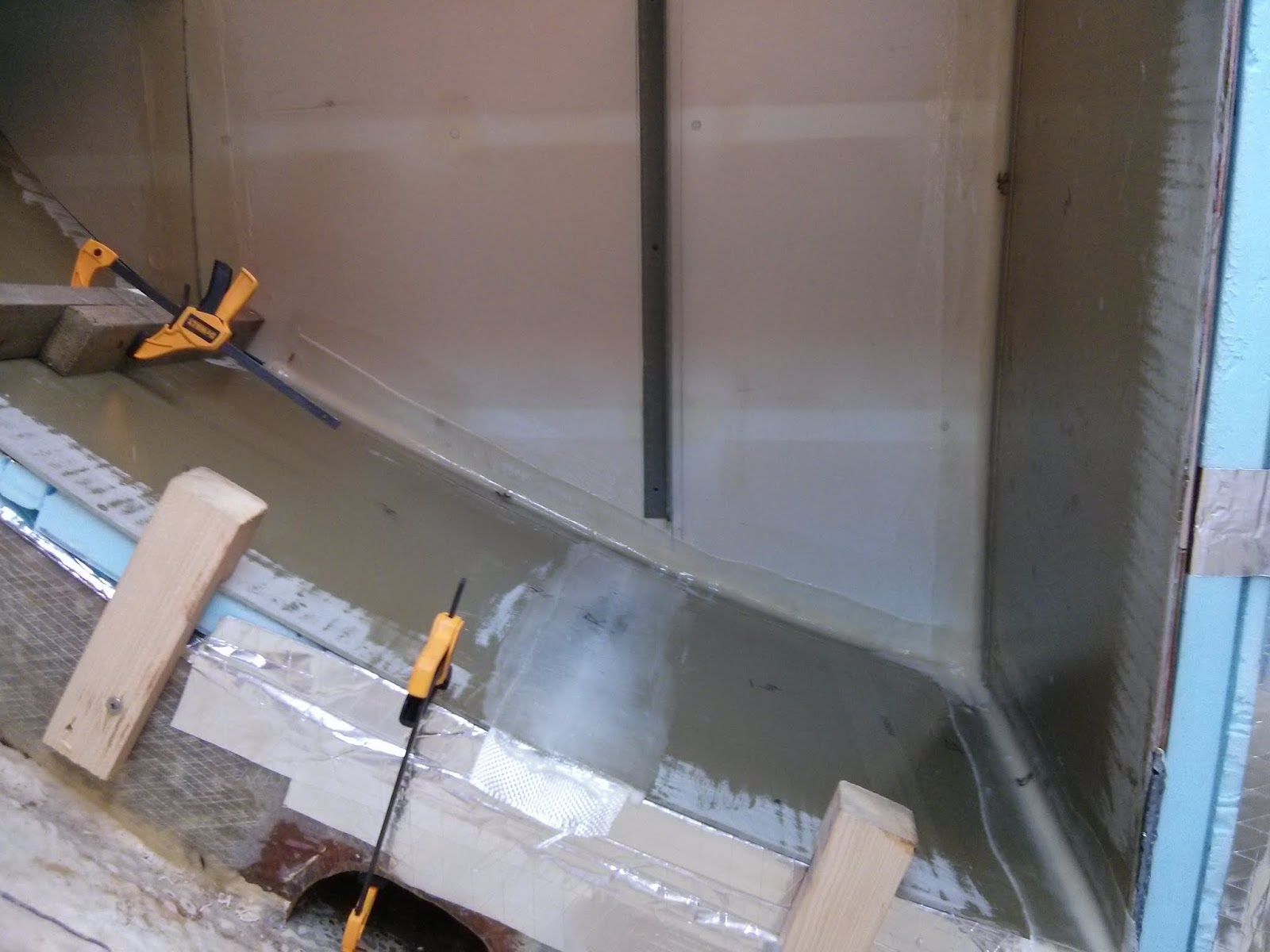
Using 6oz fiberglass cloth over thickened epoxy to structurally join the ice box panels. 

The three butt joints (floor, forward wall, and ceiling) were filled with thickened epoxy and then covered with a 3” wide strip of fiberglass cloth.

Once cured the epoxy and fiberglass combination created structurally sound, watertight joints with a rough faces and irregular edges.    If left in this state the fiberglass joints would be difficult to clean and aesthetically unpleasing. 

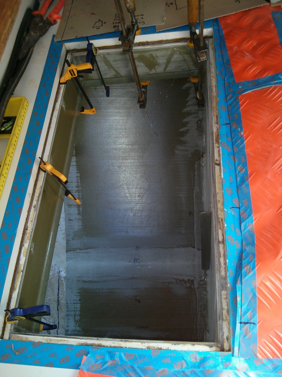
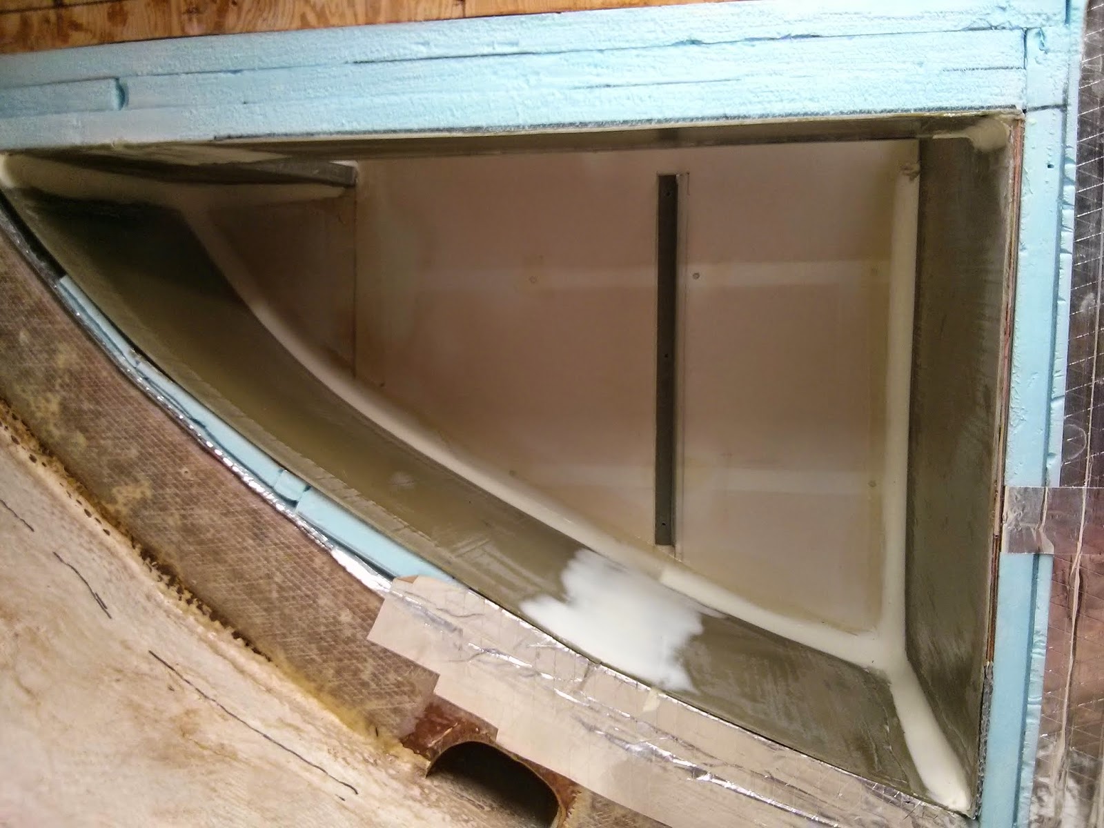
Time for fillets and fairing. 

Fillets equate to filling an angular inside corner with thickened epoxy to create a nice even radius between the two faces.
Round on of  fairing and fillets applied.
Fairing is laying thickened epoxy (or other fairing compound) atop a rough or irregular surface in an effort to smooth the surface and hide any irregularities.

For the ice box project I used West Systems Epoxy thickened with a generic brand of micro-balloon filler (similar to West Systems 410).  This type of fairing filler adds little strength to the joint, but it sands easily and creates a smooth even surface.

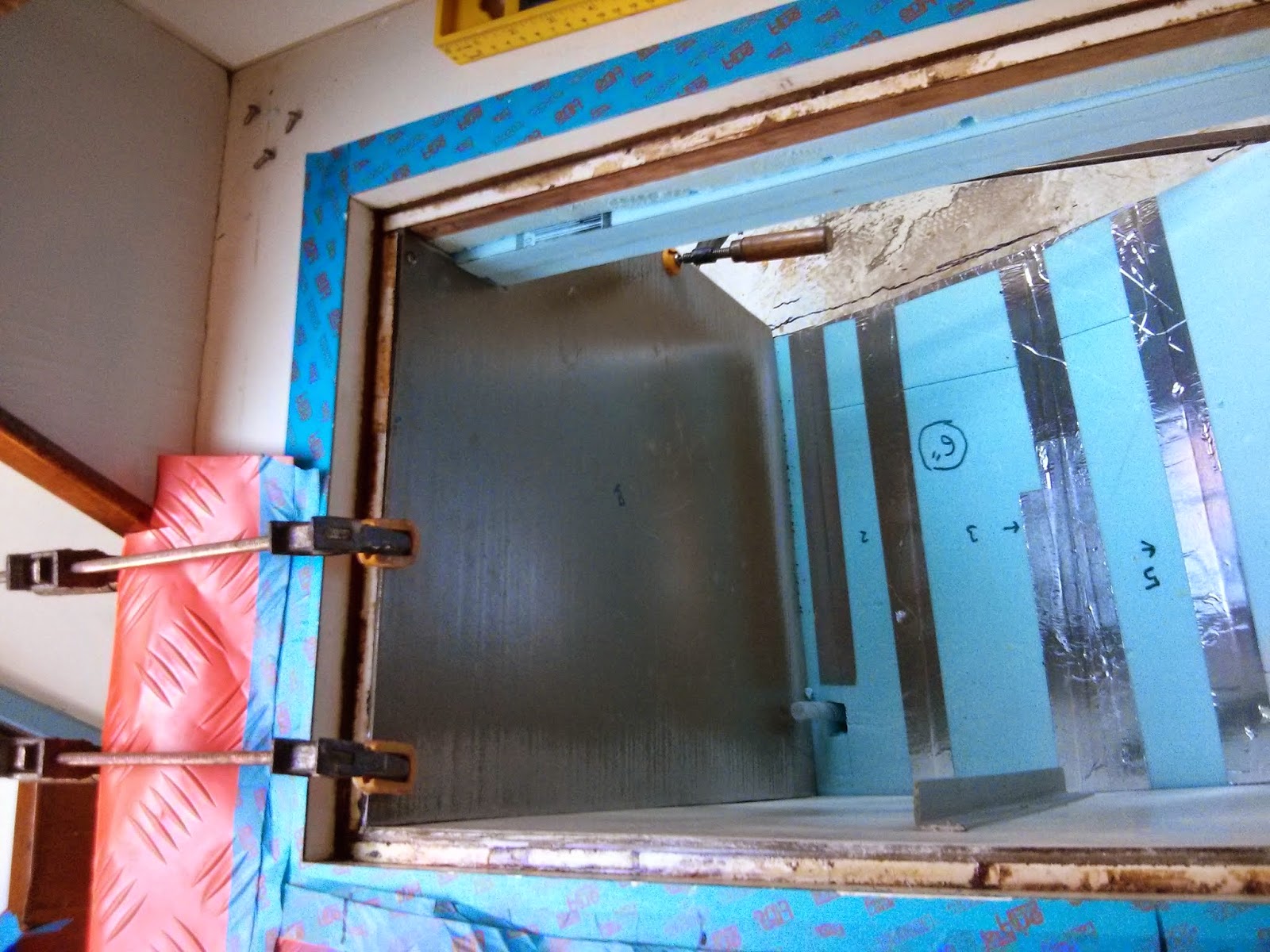
Round one of fillets and fairing after sanding with 80 grit paper.

When applying fairing or creating fillets I prefer to begin by spreading the wet epoxy out scrap piece of cardboard, approximately one foot square, similar to a painter’s pallet.  Spreading the epoxy out extends the working time and working off the “pallet” creates less mess on the spreaders.
Various spreaders used in ice box project.

The choice of spreader is dictated by the dimensions of the surface to be faired or the size of fillet to be created.  Unable to find a spreader to match the fillets I wished to create in the ice box, I cut down a larger plastic spreader to the desired size. (small yellow spreader on left in image above.)

Another method of applying epoxy to a corner for creating fillets is the “icing bag” technique.  Place the thickened epoxy into a thick walled plastic bag (or two).  Cut an opening slightly smaller than the fillet you wish to create in one corner of the bag.  Start with a small opening; it can always be made larger if needed.  Twist the top of the bag to seal. Apply pressure to bag or continue to add twists to the top to force epoxy out the small opening.  I’m certain there are better descriptions of this technique with images and videos available on-line.  I chose not to use this method for the ice box because the desired fillets were very large.
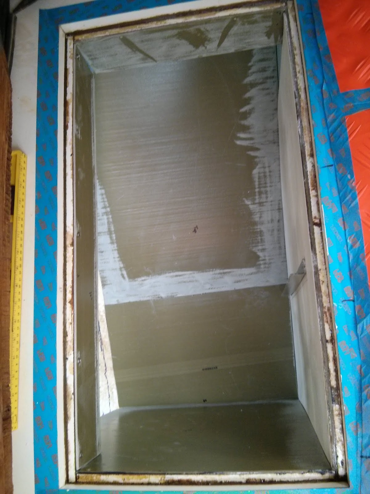
Large fillets in ice box will make cleaning easier.
Applying fairing and using the spreader to smooth out the fillets is akin to icing a cake.  To carry the icing analogy further… just as the world has cadre of pastry chefs and artists that can create wonders with icing, there are individuals with the ability to efficiently and deftly apply thickened epoxy to a surface and create long, flawless fillets.  My skills have not yet evolved to this point (doubtful if they ever will.)  If you desire additional instruction in applying fairing or creating fillets, then again suggest searching the internet or youtube.

Each application of fairing is followed by a round of sanding.  The first and second rounds of fairing, I used 80 grit sand paper to quickly remove excess material.  On the third and final round of fairing, I used 80 grit paper to eliminate a few rough spots then switched to 120 grit.
Three rounds of filling and sanding complete.  Now read for primer.
The plan is to paint the majority of the interior of the box prior to installing the aft wall.  This will create two rounds of fairing and painting, but I believe the finished product will be of higher quality if the painting is not done while hanging into the box from above.
Three rounds of filling and sanding completed.  Now ready for primer.

The next step is to fit the aft wall of the ice box in place so it can be painted prior to installation.  It is also time to begin work adding insulation to the lid.

More images and notes from this on-going project as available in the Ice Box Rebuild Photo Album.


Sunday, April 19, 2015

Installing Ice Box Interior Panels - Part 2 - Defying Gravity

It is difficult for me to describe how mentally I go about generating solutions. Sometimes just sitting and staring at the problem helps.  Other times I need to walk away and focus on other tasks.  I ask others.  I search the internet.  I wander through bins of scrap parts.  I push sandpaper around on the latest project. There is always sanding to be done.  Eventually, if I keep the mental wheels turning a solution materializes.  

Finding a method of installing the ceiling portion of the ice box took some time. I struggled with overcoming gravity... clamping or temporarily securing the ceiling panels for long enough to allow the epoxy to set. The foam insulation did not provide any point for mechanical fasteners.  The smooth, arc of the floor panel prevented propping up the panels.  The true ah-ha, light bulb moment, came when the idea hit me to use prefabricated FRP angle for the outside corner where the vertical surface of the ice box opening meets the ceiling.   Whew, I know that last sentence was difficult to visualize.  Let me provide a few images.
Stock image of prefab FRP angles
Structural FRP (fiberglass reinforced plastic) is available in sheets, tubes, channels, angles, and many, many other shapes.   I purchased two 60” long sections of 1/8” thick 90 degree angle with 1” wide legs from McMaster-Carr.

Once cut to fit, I coated the inside faces of the angle with thickened epoxy.  The 1/8” FRP ceiling panels fit under the horizontal leg of the angle.  The vertical face of the angle fit against the vertical panel in the access opening to the ice box. 
clamping the FRP angles in place also secured the ceiling panels.
The outside face of the angle provided a clean surface for clamping the assembly in position.
The counter top view of clamping the angles and ceiling in place.

Using the prefab angle has the added benefit of creating a clean outside corner on the interior of the ice box.  This saves me from having to apply a strip of fiberglass cloth and multiple rounds of fairing on the outside corner.

I plan to paint the interior of the ice box prior to installing the aft wall so next up is fillets and fairing.


More images and notes from this on-going project as available in the Ice Box Rebuild Photo Album

Saturday, April 11, 2015

Installing Ice Box Interior Panels - Part 1

Even after months of lying flat under 30+ pounds the forward interior panel, reclaimed from the original construction, maintained a stubborn, concave curve.  The curve would make installing the panel an epoxy coated clamping nightmare.   

Glassing a prefab, 1/8” thick FRP angle to the panel eliminated the curve.  We plan on installing an acrylic divider between the freezer and fridge sections of the box.  This angle will serve as the attachment point for the panel.

Attaching a 1/8" thick FRP angle to the forward ice box panel.

Clamping the panel into a flat plane took a bit of effort.  The angle was held in place by three screws driven into a scrap 2" X 4" on the opposite side of the panel.  These screws were later removed their holes filled with epoxy.

The using a combination of clamps and screws the fore and mid-ship panels went into place relatively easily. 

Clamping the mid-ship panel in place while epoxy along the top edge cures.

Unfortunately floor panel would pass through the either the top of aft openings as a single piece and had to be cut.

Dry fitting the two floor panels.

Giving in the Don Casey’s sage advice about refrigerator drains in This Old Boat (a fine resource which I frequently consult), I eliminated the drain.  After many sleepless nights spent pondering the best method for installing an ice box drain that would never leak and never require maintenance,* I gave up.  I pulled the ½” hose and back-filled the insulation.

The forward side of the floor panel fit neatly under and was held in position by the vertical forward panel... as if somebody planned it... a success story from my sleepless nights pondering ice box design.* Prior to applying fillets and cloth to the interior corners, it would be necessary to clamp the aft edge into the proper location.

Improvised clamps fabricated from a scrap 2" X 2"

Necessity is the mother of invention.  Using some scrap 2X2 lumber, I created “L” shaped pieces that hold the panels in place by temporarily screwing them into the rib along the hull.

Using a bit of creativity to clamp the interior panels.

These also served as an anchor point for pressing the forward panel into position.

Looking down through the counter top.

The inside corners received a fillet of epoxy thickened with cabosil followed by a strip of 3” wide, lightweight fiberglass cloth.  The butt joints in the floor and fore panels received a bead of thickened epoxy, a strip of the 3” fiberglass cloth, and finally a heavy spread of thickened epoxy. 
fillets and fiberglass cloth along the inside corners and seams.

The clamp along the fore panel prevented me from glassing the full length of the floor joint.  Glassing the upper section will be completed when the clamps are removed.


More images and notes from this on-going project as available in the Ice Box Rebuild Photo Album

*Ok, many sleepless nights may be an exaggeration.

Thursday, April 9, 2015

Blister Repairs 2015 Session

Removing Pilgrim’s remaining bottom paint revealed 38 previously undiscovered blisters.  Unlike last summer’s blister & hull damage repairs (photo album – Hull Damage & Blister Repairs 2014), the blisters discovered recently are not linked to ill fitted or ill tabbed internal structures exerting focused pressure on the hull.  Nor did any of them lead to delamination or areas of cloth lacking resin. 

With the bottom paint gone, tiny seams or pock marks in the hull provided the evidence of an issue.  Following the evidence with a grinder typically lead to a void a short distance into the outer copped strand mat layer. None of the blisters were wet, but Pilgrim has been on the hard for nearly 18 months so this was not surprising.  Generally the blisters were minor… smaller than the palm of my hand and penetrating only into the outer layer of mat.

Two notable exceptions were along the port keel.  These areas were larger in size and the damage extended to the outer layer of woven cloth.
Two large blisters on port keel.
These two may be linked to hull stresses as they are located along the transition from solid lead ballast to the hollow section of the keel.

While no area of the hull was completely blister free, the starboard hull had a line of blisters extending from the cockpit area to around mid-salon area and just below the waterline.
Line of blisters along starboard hull just below the waterline.
12 of the 38 blisters were deep enough to require additional mat for repairs. I developed a fancy system for identifying which areas required glass matt and which simply needed filler.
Group of three blisters on the starboard waterline

I’ll bet the readers of this blog are savvy enough to figure out my system from a single photograph.

Our system for repairing the blisters followed the same steps we used last year.
Cutting 1708 cloth for blister repairs.
Apply one or more layers of 1708 cloth to hull
Ready for the grinder.
After curing – wash, rinse, grind with 36 grit disc, wipe down with acetone.  Then fill the area epoxy thickened with a combination of milled fibers & cabosil.  Areas not requiring fiberglass cloth (see blister in center of image above) start the repair process with an application of thickened epoxy.
Ready for sander.

After curing – wash, rinse, sand with 80 grid paper in orbital sander, wipe down with acetone.  Apply first application of epoxy thickened with fairing filler.
Ready for hand sanding.
After curing – wash, rinse, sand lightly with 80 grid paper in orbital sander, hand sand with 80 grit paper on large block, and wipe down with acetone.  Second application of epoxy thickened with fairing filler.

After curing – wash, rinse, hand sand with 80 grit paper on large block, wipe down with acetone.
Ready for barrier coat  :-)

While sanding fairing I developed a second, highly evolved system of identifying the areas completed.  Once again I’m assuming readers of this blog can deduce my system from a single photograph.

The next step, yet uncompleted, will be to overcoat the entire hull with 5 to 7 coats of barrier coat.

For more images and notes from this project check out our Bottom Job Photo Album.

No back to that lingering Ice Box Rebuild.


Thursday, April 2, 2015

Bottom Paint Removal

In fall 2004, my initiation into boat ownership began by sanding bottom paint off a Cape Dory Typhoon.

Fall 2004 - backyard bottom job on 2nd Chance. 
Blisters filled and bottom paint gone... time for some barrier coat.
She made the road trip to FL in a fresh application of barrier coat.
Since then I have spent many days driving orbital sanders and disk grinders in pursuit of a bare hull.  Determined there must be a better way…  I researched chemical strippers.  These all appeared fraught with a new realm of mess and hazards.  Soda or sandblasting appears to be a good alternative, but hiring out the job ran against my DIY grain.  I could find no one was willing to load out the extensive and expensive blasting machines. 

A friend of ours in Beaufort with decades more boat experience than I suggested using a very sharp chisel or scraper (Thanks TD).  I recalled a recent Practical Sailor Article (“Digging Into Bottom Paint Removal” March 2014) that also favored using a very sharp scraping device.

With nothing to lose, I collected an assortment of impliments. After some experimentation with chisels, putty knives, paint scrapers, etc.  I found my weapon of choice to be a stiff, 3” wide scraper with a 20⁰ angle in the blade.
Permanently stained bottom paint blue from the task. 
The model I settled on was purchased from Lowes Hardware.  The business end must be sharpened to a knife-like edge and this edge maintained frequently during the removal process.  I set up a sharpening station with a bench grinder and whetstone just outside the tented hull.  A little time behind the scraper and it will be obvious when the tool begins to lose its edge.

The layers of bottom paint come off the hull in large (pea to dime size on Pilgrim) flakes rather than the fine dust generated by sanding or grinding.  Care must be taken to avoid gouging into the substrate below the bottom paint.  

Working in approximately four foot wide strips vertically along the hull, I used the blade to remove the bulk of the bottom paint.  I then revisited the area with 80 grit paper on an orbital sander.

I am a convert to the use of a scraper for removing bottom paint.

Tinted blue and sweating despite the comfortable March temps. 
It took me eight hours split over two days to remove the remaining bottom paint from Pilgrim’s hull.  The job is still a messy, taxing affair that requires every effort to avoid contact with bottom paint.  I don disposable coveralls, a cotton balaclava, a 3M full face mask with particle filters, and heavy duty rubber gloves for the job. 

Looking down the exposed hull.
I am pleased the task of removing Pilgrim’s bottom paint is complete.  We can now move forward with repairing 38 newly uncovered blisters… to be continued.

For more images and notes from this project check out our Bottom Job Photo Album.